Welcome to the Corvette Forums at the Corvette Action Center!

Custom Bi-xenon headlights FINISHED!

Peer81

Well-known member
Joined
May 21, 2003
Messages
2,497
Location
Netherlands
Corvette
'81 Black
Hello Everybody,

I'll also post this project overhere because most forummember aren't following my '81 project in the L81 section.
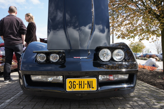
Well as we all know the OEM headlight system is preforming under average so something began boiling in my mind to change it.
This was back in '07 or '08. At that time xenon (or HID) was only to be found on the more expensive cars but when a xenon car was passing me in the dark it was like the sun came up again. So I had to do something with xenon (HID). Also around that time here in Europe the new Alfa 159 was introduced with some very good headlights. So I drew up a sketch and began my search on ebay. Ebay Germany sold some Bosch Bi-xenon units that came out of BMW or Audi's. The thing is that these projectors are only 3" wide and not the OEM 5.75". So the headlight assembly didn't need to pull up to high and I needed to fab a new shroud for around the projectors. After a few months I had collected 4 Bosch Bi-xenon units with the rights ballasts and ignition modules.

IMG_4416.JPG


IMG_4417.JPG


IMG_4418.JPG


Somewhere in ' 09 I found a nice Alfa 159 headlight assembly for the right price.
I'm only going to use the two biggest lenses to fit around the xenon projectors to protect the projector lenses.
So cutting it up was the only solution. :)

IMG_4901.JPG


IMG_4902.JPG


IMG_4903.JPG


Another 2 years passed doing other stuff but then I had time and a spare alu headlight assembly to fabricated the projectors in them. Cutting away a lot of aluminium and with some home made brackets (that I can adjust to level the projectors) I was able to connect the projectors to the assembly.

IIMG_1651.jpg


IIMG_1650.jpg


IIMG_1652.jpg


IIMG_1653.jpg


Part one :)

Greetings Peter
 
Part 2.

IIMG_1654.jpg


IIMG_1655.jpg


Testing the projectors in the kitchen :)

IIMG_1839.jpg


IIMG_1840.jpg


IIMG_1845.jpg


Problem with xenon is that it only uses one light bulb. A C3 uses two lightbulbs, one for low beam and a different one for high beam. So with the OEM wiring and the xenon in place switching from low beam to high beam the projectors will turn off! So I need to find a solution for that problem.

Testfitting the projector assembly in the spring loaded assembly.
It's very tight but can be done!

IIMG_1993.jpg


IIMG_1998.jpg


IIMG_1999.jpg


IIMG_2000.jpg


IIMG_2001.jpg


IIMG_2003.jpg


Greetings Peter
 
Part 3.

As the headlights didn't have to go up that high anymore I had to make some new front links. BBShark at vettmod.com already redesigned the front link for lower headlights so I altered his for the height I needed. Cor was so kind to fab the links for me. My compliments go out to BBShark and Cor! :upthumbs

This is a trail version.
IIMG_2022.jpg


Here you can see in the new situation the assembly goes up only 13cm as OEM goes up 17.5cm.

IIMG_2012.jpg


Fitting the xenon units in the headlight assembly with the new front link wasn't that easy.
In the closed position there isn't a problem. You can see I need to adjust the front link a little so it hits the low position bolt better.

IIMG_2025.jpg


But the open position is a problem. The front link is hitting the metal xenon bracket. No problem I can still adjust it to make it fit. But the outer spring is hitting the xenon solenoid and the metal spring retainer is also very close to the solenoid.

IIMG_2026.jpg


I tried swapping the springs so they cross each other. Not a perfect solution but it helps a little.

IIMG_2030.jpg


In the fall of '12 I had some more time for the xenon project.
I needed to change the lever on the headlights so it will not open more then 13.5cm (original it's around 17.5cm I think). A good friend of mine wanted to make the levers and so he did. Just perfect!

IIMG_2034.jpg


Of course with the new lever it still didn't fit well as one spring was still hitting the solenoid print. By heating the spring and turning the hook around it just did the trick. :)

IIMG_2035.jpg


IIMG_2036.jpg


I also changed the center pin a little so the springs will be closer together.
As long as they aren't binding it isn't a problem I think.

IIMG_2038.jpg


IIMG_2039.jpg


Greetings Peter
 
Nice one Peter.. :thumb

As a suggestions for those who are interested, they might want the part numbers you used? Aside from the fabricating.. :)

I am surprised the Dutch MOT is ok with it, or are they?

:w
-Stefan
 
Very interesting approach. I like it!!

Mac
 
Thanks Mac :)

@Stephan, don't really have part numbers but this is what I've used to make it.
4x AL Bosch Bi-xenon projectors (BMW E46)
2x Alfa Romeo 159 Headlights
2x Custom handmade shrouds
2x Wolstentech relays
4x 20 amp fuses
2x 30 amp fuses
2x Custom front links
Custom wiring from alternator to headlights.

To continue with the project.

I altered the spring to it wouldn't contact the solenoid print.

IIMG_2040.jpg


IIMG_2041.jpg


At the end of October 2012 I test fitted the xenon unit in the vette. Hooked the wiring to the original wiring just for the test. There will be a better new wiring for the units in the car with two relays so all the power will not go through the light switch. The light switch is only used to trigger the relay and power will come directly from the 12v wire from the alternator.

IIMG_2500.jpg


IIMG_2496.jpg


IIMG_2490.jpg


IIMG_2491.jpg


IIMG_2492.jpg


Begin November 2012 I still had to change (or shorten) the center pin a little. As the spring was hitting the print the assembly will only open 12.5 cm and not the 13 to 13.5cm it should do. Spring are just slightly touching each other but not a big problem so far.

IIMG_2506.jpg


I cut open an old (or new..) headlight shroud that I bought on ebay. This is a little mockup from how it should be.

IIMG_2507.jpg


IIMG_2509.jpg


IIMG_2510.jpg


Greetings Peter


I thought I had space for the ballast under the hood around the headlights but that isn't the case so I moved them to the other side. The ballasts are waterproof by themself but just in case they will be covered with a plastic bag made from thick truck plastic.

IIMG_2512.jpg


As the wiring from the ignition system to the HID / xenon bulbs is very short I had to place them very close to the bulbs. Just had some space left next to the xenon assemblies.

IIMG_2513.jpg


IIMG_2514.jpg


Had some time after christmas 2012 to make a new shroud that fits the new xenon units. Still not finished but this is a mockup and we can make a contramockup from this with polyester and from the contra mockup we can make the final shroud from polyester.


IIMG_2518a.jpg


IIMG_2519a.jpg


IIMG_2520a.jpg


IIMG_2521a.jpg


IIMG_2522a.jpg


For the wiring I bought some nice fuses to protect the system. The main fuses will be 2x 30amp and the individual fuses 4x 20amp for each xenon unit one.

fuseholder.jpg


And the relays came in. Problem with the xenon is it is the same bulb for normal and full headlights. On the Corvette when you switch to full headlights the normal ones will go out as power is cut. These relays solve this problem.

IIMG_2533.jpg


Greetings Peter
 
2013:

First I put some clay and putty on the edges to give the mockup some round edges (sorry this is the mockup frame and not the contra molding).

IMG_5331.JPG


IMG_5333.JPG


After some more sanding, putty, sanding and putty etc etc the mockup was ready.

IMG_5337.JPG


I also begun on the wiring for the xenon (HID). This is the one on the passenger’s side. From left to right, in red the premium fuse (30amps but can bring it down safely to 20 amps). Second to the left is the Wolstentech relays, this thing keeps giving current to the headlight even when I switch from low to high beam and back. It also gives me the option to delay when the headlights are turned on or when going out up to 30 sec. So I can first let the headlight come up and after that the lights will turn on (just an example). On the right are the two secondary fuses (15 amps, can go down to 10 amps) for the left and right headlights on the passenger’s side. After that the current goes through the tiny oem bmw wires to the switches and ballasts.

IMG_5339.JPG


IMG_5350.JPG


IMG_5351.JPG


IMG_5352.JPG


Sorry don't have any pictures making the contra molding from polyester.
Used some old polyester so the contra molding is much thicker, on the other hand also much stronger than normal. In the process the original mockup couldn't be salvaged but this is the contra molding on the outside (that isn't going to be used!).

IMG_5353.JPG


Inside:

IMG_5356.JPG


Then again, a lot of putty, sanding more putty etc etc, several layers of base paint and waterproof sanding to get it right.

IMG_5357.JPG


Greetings Peter
 
Making the final frame inside the contra molding. This is a picture with 2 or 3 layers polyester.

IIMG_5359.jpg


With an extra layer.

IIMG_5360.jpg


And the final product. Lucky for me, I put on the final layers in the morning and we already tried to take it out of the molding in the evening. This way the polyester was still flexable that way it was possible to get it out, if the polyester had been hard then the only way to get it out was to destroy the contra molding. Now I can make a second copy in case something goes wrong with the first one, of course I'll also save the contra molding. So in the front the new shroud and at the back the original one :)

IIMG_5363.jpg


IIMG_5364.jpg


So then the basic shroud in the vette

IMG_2547.jpg


IMG_2548.jpg


IMG_2549.jpg


It was a lot of sanding, filling, sanding, painting, sanding etc etc but this is the end result of the passengers side. Still the BMW projects, ALFA bezels and custom shroud.
It only needs a final black paint job (and at that time the vette some TLC! :D)

IMG_5404.JPG


IMG_5405.JPG


At our annual first meeting of the year I put in one original headlight and the HID headlight next to each other so you can see the difference.

02380a90.jpg


Greetings Peter
 
Here you can see the wiring on the drivers side for the HID units. From right to left. In red the prime fuse, next the wolstentech relay and left the two fuses for each ballast on that side (of course the passengers side has the same wiring setup).

IMG_5407.JPG


Now its "just" some work to mirror everything to the drivers side. Here you can see the headlights upside down with the ignition system in place.

IMG_5408.JPG


And the last picture so far. On the drivers side also the HID system but without the custom shroud (because I still need to fabricate it)

IMG_5410.JPG


And last what 4x HID looks like in the dark (no way you can beat this with standard halogen)

IMG_5422.JPG


Next to do was the driverside headlight. First installed the wooden rings around the HID units.

IMG_5436.JPG


After that I just "mirrored" the other shroud.

IMG_5438.JPG


Then the same as the first, began with blue clay to close all the holes and gave a radius to all the corners. Then work with putty and sand it back down, that again and again till it is as close as I can get it.

IIMG_2841.jpg


IIMG_2842.jpg


First made the paper/clay model just like the final piece. This way it is ready to make a negative in it from polyester. Left the final shroud (sanded ready for final paint) and right the paper/clay model.

20131101_215041.jpg


Greetings Peter
 
This time we tried to use gelcoat between the paper/clay model and the negative. Didn't work out that great, very sticky stuff and trying to separate the clay model from the negative model we had to distroy the clay model.

IMG_5442.JPG


IMG_5443.JPG


So second change but now making the final model in the negative model.
First the normal recipe, putty sanding putty sanding etc etc so the negative model is smooth and ready.

IMG_5444.JPG


Then apply some grease on the negative model, not to much because the gelcoat needs some base to stick to. But enough grease to separate the negative model from the final model.
After that a nice layer of gelcoat. The gelcoat doesn't harden that much so when I put the polyester on it the gelcoat will bond with the polyester and will turn into a nice white layer on the outside of the final model.

IMG_5445.JPG


Polyester stuff on it and wait a few hours to let it cure.

IMG_5446.JPG


After a few hours (when the polyester isn't fully cured) the separation begins. As the polyester is still somewhat flexable it's easier to get it out of the negative model. Or at least, that was the plan... After 3 hours working on it with screwdrivers, puttyknives and other stuff they were still bonded together! In the mean time i distroyed the gelcoat as I tried to separate the two. The next day a friend tried to take them apart, still no way! So in the end the only thing we could think of was to grind the final model into pieces to save the negative.

IMG_5447.JPG


In the above picture you can see the gelcoat still sticked to the middle part of the model and in other places the smooth surface is pretty much distroyed! So back to the putty, sanding action. After a week the negative model was back where we started..

IMG_5448.JPG


Our conclusion, gelcoat is nice for big and simple models but not these small the heavily curved things. So next time no gel coat!

2014:

This time only loads of grease in the negative model. An extra layer polyester to make it extra thick. This time after 3 hours the outside was solid and wasn't sticky anymore, so with two putty knives I took the final model out of the negative without to much problems.

IIMG_3095.jpg


On the left still the final product (sanded for final paint) and on the right the driversside final model (still with alot of work to do)

IIMG_3096.jpg


As the model wasn't perfect I fabricated some extra polyester left and right.

IMG_5452.JPG


And then after hours of sanding and putty ready for painting (first round)

IMG_5453.JPG


First layer paint was white. Very think so I could sand all the ups and downs out of it. After that 2 layers 2 component black, sanding it with 400. After that it looks like this before the final paint job.

IMG_5456.JPG


Greetings Peter
 
You can still see some small reflective black dots (low points). This is as perfect as I can make it. With the new paint layer there is no way you can see the low spots.

IMG_5457.JPG


After this I test fitted the assembly. Seems like the alu headlight piece wasn't perfectly as it was below the body at the rightfront. We had to give it a 2 to 3mm putty layer in the right corner to make it fit perfectly. And when you're busy with putty why not check the other piece to see if it is good enough. Well, yes again sanding putty sanding putty. Will it ever stop?

So THIS IS IT!
I have to say, it took a while and some hours. But I'm very happy with the result and also proud!
With the lights on:

IMG_5468.JPG


The light changes color from blue to white to "little yellow" white. When the lights get older (and more hours) they change back to blue-ish. You can see that the left ones are yellowish white and the right one more blue-ish white. At the end they should all be the same blue. New model lights don't change color anymore.

And lights off:

IMG_5473.JPG


IMG_5476.JPG


IMG_5478.JPG


Today some nice weather so washed all the dust off it and this is what it looks like at daytime :)

IMG_5479.JPG


IMG_5480.JPG


IMG_5481.JPG


IMG_5482.JPG


IMG_5483.JPG


IMG_5484.JPG


So finally after some years this project is finished!

Greetings Peter
 
Very nice manual for other people to update theirs to Xenon..

I truly admire your persistence Peter.. Goed Werk!!! :BOW

:w
Stefan
 

Corvette Forums

Not a member of the Corvette Action Center?  Join now!  It's free!

Help support the Corvette Action Center!

Supporting Vendors

Dealers:

MacMulkin Chevrolet - The Second Largest Corvette Dealer in the Country!

Advertise with the Corvette Action Center!

Double Your Chances!

Our Partners

Back
Top Bottom