the least problems and best power can be reached thru an increase in displacement & compression ratio ,most engines can make about 1-1.2 HP PER CUBIC INCH OF DISPLACEMENT in street strip condition useing the components easily available and the use of BETTER FLOWING CYLINDERHEADS (INSTALLING a STROKER CRANK ASSEMBLY or LARGER SHORT BLOCK, increases the displacement & can increase the compression ratio) the better flowing cylinder heads (and porting your intake) will allow you to make a good deal more power.
if a 350 makes 1.2 hp per cubic inch is making 420hp a similar 383 will make 460hp
this is the type of challange/upgrade I work on for the guys all the time, AND IM CERTAINLY NOT SUGGESTING YOU CAN,T REACH YOUR GOAL,THRU OTHER ROUTES, BUT THAT APPROCHING THE PROBLEM LOGICALLY ITS FAIRLY EASY TO PLAN YOUR GOALS AND COURSE TO ACHEIVE THEM,
the first thing youll need to get strait in your mind is the realistic budget youll be willing to work with and that performance is basically the result of the power to weight ratio and HOW effectively you can get the power to the ground.
keep in mind that for a street car your NOT building the engine for max peak power, your looking to build for the best average power/tq curve over the rpm range youll use most
AND THAT HAVING SLIGHTLY MORE HP THAN THE MINIMUM REQUIRED IS SMART, simply because you won,t always have the ideal tune or traction available,its silly to shoot for minimum levels yet its a waste of money to over build the engine, to levels youll seldom use or even want, as theres always compromizes in driveability
ok first Id point out that its silly to build anything smaller than a 383 displacement simply because youll make significantly greater total power from a larger engine than a smaller one,COSTS for a 383 are just not that much higher than a 350, and its TOTAL POWER not horsepower per cubic inch your interested in!
next,CORRECTLY MATCHING the cylinder heads, cam and compression ratio , to the rpm range where youll get the best results is where youll make most of your power potential.
think it thru before buying parts, and only sellect those components that match your goal,by far the most comon mistake is randomly sellecting mis-matched parts because you "GOT A DEAL"
ok lets look at your options, to keep costs reasonable we want to use what we can from your current engine but its insane to limit yourself to parts that restrict your potential power levels severly like the current heads,intake and rear gear ratio.
the formula for hp is (tq x rpm/5252=hp
example
450 ft lbs of torque at 3000rpm=257hp
450 ft lbs of torque at 6000rpm=514hp
because the torque is available at that higher RPM RATE and at the higher rpm useing gearing the rotational force the engine supplied can be applied faster or slower to the rear tires
[color:"red"] here read these ALL CAREFULLY [/color]
http://www.69mustang.com/hp_torque.htm
http://www.ubermensch.org/Cars/Technical/hp-tq/
http://vette.ohioracing.com/hp.html
http://auto.howstuffworks.com/engine1.htm
http://auto.howstuffworks.com/horsepower.htm
http://auto.howstuffworks.com/question622.htm
where most guys go wrong is in not correctly matching the cars stall speed and gearing to the cars tq curve, if you mod the engine for increased high rpm performance but fail to also match the stall speed and gearing to that higher rpm tq curve much of the potential improvement is wasted.
calculate, your minimum hp levels needed
http://www.runeb.org/www_docs/Jexoticasite/frames/horsepowercalc.htm
http://www.stealth316.com/2-calc-hp-et-mph.htm
http://www.gordon-glasgow.org/hpcalc.html
a few calculations will quickly point out that your realy looking to have between 350-400 rear wheel hp, that basically translates into an engine making about 18% higher power at the flywheel, so lets assume or goal is a 420-450 hp engine, now your basic 383 will be correctly designed and matched to a rear gear ratio in the 3.73-4.11 rear gear so youll maximize the area in the torque curve that can give the best results, the 2500-6000rpm band. so thats where we NEED TOO concentrate our efforts. this should point out the stall speed of about 2500-2800rpm is ideal in this application to match your needs
look at this chart, it shows the ideal durration for best results at differant rpm bands, well want the MINIMUM DURRATION that will supply our needs thats going to be in the 220-230 range for street use,while the 230-235 range would be about ideal for power.
we quickly find that durration will match to a 10:1-10.5:1 cpr if we want to use pump gas.
ok,now the CYLINDER HEADS and intake NEED to supply that RPM RANGE and DISPLACEMENT, youll want a set of heads that flow about 230cfm AT .500 lift at the least,to easily match that requirement.
currently this is a good choice in performance per dollar in heads
heads
http://www.jegs.com/webapp/wcs/stores/se...7&langId=-1
cam
(READ THIS)
http://www.idavette.net/hib/camcon.htm
(minimum cost flat tappet hydrolic)
http://www.crower.com/misc/cam_spec/cam_finder.php?part_num=00231&x=35&y=13
http://www.cranecams.com/?show=browsePar...rtType=camshaft
upgraded ROLLER CAM
(what IM useing in my similar engine)
http://www.cranecams.com/?show=browsePar...lvl=2&prt=5
(what ID use if I was to build it again)
http://www.crower.com/misc/cam_spec/cam_finder.php?part_num=00471&x=20&y=9
stroker kits
http://www.speedomotive.com/383%20Mighty%20Mouse.htm
http://www.speedomotive.com/383Forged.htm
oil pan
http://www.midwestmotorsportsinc.com/order_part.php?item=CP100LT&line=MWM
to answer some questions
WHATS REQUIRED?
installing a longer 3.75 stroke crank assembly
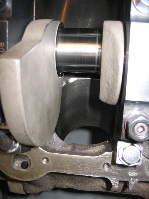
Ive built dozens of 383 and 396 sbc engines and the clearancing can be done BY YOUR OWN HANDS with a standard HAND HELD drill and a few CARBIDE BURRS OR GRIND STONES in that drill in well under two hours if you take your time and total expence even if you need to buy that drill and burrs will be well under $50 total
http://www.click-onsource.com/Merchant2/merchant.mvc?Screen=CTGY&Category_Code=O VAL_1-4_Shank
buy a 1/2" burr and a cheap drill
http://cgi.ebay.com/ws/eBayISAPI.dll?ViewItem&category=20776&it em=4358782476&rd=1
place you old bearings in the block an place the crank in those bearings after coating them with axle grease
slowly rotate the crank and grind a minimum of .060 clearance anywhere the counter weights might touch the block and try NOT to grind more than about .070 any place it touches the block (use a JUMBO size paper clip as a gauge if you don,t have feeler gauges)
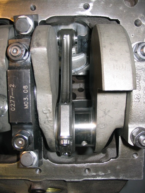
next assemble two connecting rods and pistons, one connecting rod and piston for the left one connecting rod and piston for the right, use old bearings coated with axle grease and no rings on the pistons, assemble them to the crank and grind anyplace the rods touch the block, grind minimum of .060 clearance and try NOT to grind more than about .070 any place the rods touche the block (use a LARGE size paper clip as a gauge if you don,t have feeler gauges)move them to the next journal and repeat untill all 4 journals and 8 connecting rods clear. now assemble all eight rods and pistons without rings and install them in thier correct locations and recheck everthing carefully.
next intall the cam and index it correctly with the timeing chain/gears, rotate the engine slowly and look for clearance issues, between the cam and rods/rod bolts ,youll need to use a small base cam if there are major clearance issues but in most cases if your cams lift and duration is under about 230 at .05 and .500 lift there should be minor if any clearance issues, usually the outside edge of a rod bolt head is the only area needing a touch up.
once everything clears, wash all the parts VERY CAREFULLY ,TWICE and re-oil then send out to be ballanced now you might ask why do that! well, first youll know its done correctly, and that a correctly built 383 will have a very significant hp and torque advantage over any similar 327 or 350[/b]
how much power I'll get.
that of couse depends on the combo, cpr, cam,ETC. but you can assume about a 40hp/40 ft lbs increase over a similarly built 350
http://www.cranecams.com/?show=browsePar...lvl=2&prt=5
heres the SMALL BASE CAM I USE IN MY 383
NOTICE it has a .900 base circle
http://www.newcovenant.com/speedcrafter/tech/camshaft/1.htm
"The camshaft is a straight metal shaft with bumps on it. The bumps are called lobes. The gray area in the picture is the shaft's "base circle." The blue area in the picture is the lobe. The area of the base circle opposite the lobe is the "heel." The tip of the lobe is called the "nose" or "toe." (Get it? Heel? Toe?) As the camshaft rotates, the engine's valve lifters (called "followers" in overhead cam engines) ride on the surface of the base circle and the lobes. When a lobe passes under the lifter, the lifter is pushed up. The lifter is connected to the top of a valve by various means (depending on the engine), and pushes the valve open.
Between the edges of the lobe and the heel are areas called "Clearance Ramps." These are places that are higher than the base circle, but only slightly. When the lifter is on the clearance ramps, it moves very slowly. The valve is not open enough to pass any significant amount of air or exhaust, but it is open. The clearance ramps are there to reduce forces on the valve train that could tear it apart or allow the valve to slam against its seat in the cylinder head.
The distance between the base circle and end of the toe is the lift. More specifically, as you will see later, it is called the "lift at camshaft."
most cams have a base circle closer to a diameter between 1.1" and 1.2"
ID STRONGLY suggest getting a CRANE CAM thier QUALITY seems to be far better than some others I could name
a small base circle gives more clearance because your cam lobe lift is the differance between the base circle and the lobe nose, lets assume a .500 lift on a chevy sb
they normally use a 1.5 ratio rocker so the cam lobe needs to be .3334 tall , so with a standard base circle the lobe nose swings in a circle thats about 1.766 in dia.
(
a small base circle cam like my crane with its .900 dia. with the same lobe would only spin in a circle thats about 1.568 in dia. giving about 0.100 inches MORE CLEARANCE TO THE POTENTIAL ROD/CAM CONTACT AREA
Detonation vs power
some of the major factors in your engines potential power, is the volumetric efficiency (how efficiently you fill and empty the cylinders) and the octane of the fuel used, compression ratio and detonation limits,
With detonation, prevention the main factors are
Ignition timing
Quench
FUEL OCTANE
DCR
and cylinder heat level
you’ll be fairly safe if you stay under
8.5:1 dcr at 170f degrees
8.25 dcr at 180f degrees
7.8:1 dcr at 210f degrees
and keep the quench in the .036-.043 range
heres some differant calculators
http://www.kb-silvolite.com/calc.php?action=comp2
http://www.wallaceracing.com/dynamic-cr.php
http://www.smokemup.com/auto_math/compression_ratio.php
http://not2fast.wryday.com/turbo/compression/cranking_pressure.shtml
average the results
the numbers are for 92 octane premium gas run at a 14.7:1 a/f ratio
BTW heres a VERY SIMILAR GRAPH
richen up the mix to 12.5:1 for max power/tq vs low emmissions and you can cheat slightly as the cylinder temps go down slightly.
keep in mind ALUMINUM absorbs and allows the transfer of heat to the coolant at a much faster rate, so your less likely to have cylinder temps raise into the detonation range as quickly.
and it should be obvious that your igntion curve and spark strength will also effect results, personally Ive found the BETTER MSD multi strike ignitions keep the cylinders cleaner and less likely to detonate
btw, reading material
http://www.kennedysdynotune.com/Dynamic%20Compression%20Tech.htm
http://www.misterfixit.com/deton.htm
http://www.federal-mogul.com/cda/content/front/0,2194,2442_7359_7525,00.html
http://www.diabolicalperformance.com/hotrodoctane.html
http://www.sdsefi.com/meltdown.htm
http://www.procharger.com/intercooled.shtml
http://www.kb-silvolite.com/article.php?action=read&A_id=36
http://www.chevyhiperformance.com/techarticles/94138/
http://racingarticles.com/article_racing-10.html
http://www.popularhotrodding.com/tech/0311em_power_squeeze/index.html
this may help also
http://www.bracketmasters.com/small_block_stroker_383_cu.htm
http://www.prewittracing.com/newpage2.htm
need a few pictures?
this may help
the comon areas are the area near the block oil pan rail where the rod bolts touch
and the lower inner cylinder walls and where the cam lobes touch the rod bolts upper shoulder on some types of rods, now you can,t grind on the cam, but you can grind the edge of the rod bolt and you can use a small base circle cam to give greater clearances
http://www.karl-ellwein.org/2005engineprojects/388project.htm
"What do you think about hard blocking the bottom inch of the block?"
hard block porded in the cylinder base area up to the level of the bottom of the freeze plugs has little effect on the cooling and adds significantly to cylinder strength on thin bore walls, so yeah! any time you exceed about a ..040 overbore its a good idea. as it significantly strengthens the blocks walls
GOOD
http://store.summitracing.com/default.as...p;x=19&y=11
MUCH BETTER, because it gets into the fine cracks and pores in the cast block surface, as its a liquid epoxy and holds far better than the basically structural concrete that moroso sells
http://www.matweb.com/search/SpecificMaterialText.asp?bassnum=PDEVCON05
\
QUENCH??
http://www.100megsfree4.com/dictionary/car-dicq.htm
quench area:
A zone in the combustion chamber where the piston at top dead center is very close to the cylinder head. Because the piston and cylinder head is cooler than the unburned part of the fuel-air mixture (i.e., end gas), they pull the heat from the end gas. Because the end gas is now cooler, detonation is quenched or reduced. However, the process does form unburned hydrocarbons.
SQUISH
An area in the combustion chamber of some engines where the piston squishes or squeezes part of the fuel-air mixture at the end of the compression stroke. As the piston approaches top dead center, the mixture is pushed out of the squish area and this promotes turbulence, further mixing of the fuel-air mixture and more efficient combustion
run less than about .035 thousands and at high rpm levels the pistons might hit the cylinder heads, run more than about .044 thousands the QUENCH effect of forceing the fuel air mix to the center of the cylinder from the cylinders edge area looses both speed and effectiveness, remember the quench area must be so tight that virtually all the fuel/air mix is forced (squished) into the center area and none is allowed to burn untill its squirted into the burn area increaseing turbulance and burn efficiency
in theory the much better quench, combined with the shorter more compact area the flame front needs to cover and the far higher turbulance combine to allow more of the pressure to build AFTER the crank passes TDC on the end of compression and begining of the power stroke
its mostly an advantage in that you get a more even and FASTER burn in the cylinder and less chance of detonation, simply because both the lower time and faster pressure curves favor the ignition flame front vs detonation
look, it takes approximately 40 thousands of a second for the flame from the ignition to cross a 4.25" bore,at low rpms and still takes about 15 milliseconds at high RPM due to the much faster movement of the compressed fuel air mix in the cylinders, lets look at what that means
if the chevy plug is located 4/5ths of the way to one side thats a time of about 32 thousands for the pressure to build as the flame travels 3.4" in the chevy but in a compact combustion chamber it could only take the cylinder flame front less than 10-20 thousands of a second to travel acrossed the combustion chamber for a complete burn at low rpms, this of course speeds up as the swirl and turbulance increase with increased engine RPMs but the ratios stay similar. this results in more useable energy WORKING on the piston AFTER IT PASSES TOP DEAD CENTER ON THE POWER STROKE. BUT MODERN WEDGE combustion chambers use increased QUENCH to speed the flame front and lower the burn time combined with a smaller combustion chambers.
the differance may be easier to grasp if you think of the quench area as a significant part of the total combustion chamber voluum,thats forcing its potential fuel/air mix into the central combustion chamber as a jet of highly compressed F/A mix, like the differance between lighting a cup of gasoline by simply placing it next to a camp fire vs throwing it violently into a camp fire
look at this chart
http://www.iskycams.com/ART/techinfo/ncrank1.pdf
keep in mind that the cylinder pressure starts, builds to a peak and drops off all before the piston moves more than about 1/2 inch away from TDC and that if your wasteing 10-20 degrees of rotation compressing the burning mix in a slow to ignite combustion chamber your wasteing engine power
http://chevyhiperformance.com/techarticles/94138/
http://naca.larc.nasa.gov/reports/1939/naca-tm-914/
http://www.me.gatech.edu/energy/ICEngines/8_CylinderCombustionProcesses.pdf
http://www.nedians.8m.com/Comp_IC.html
http://mb-soft.com/public2/engine.html
[
LOOK CLOSELY AT THESE PICTURES
you only have QUENCH if theres a flat area on the piston that mates to a matching flat area on the combustion chamber roof, on these pistons dual quench areas throw the compressed fuel/air mix to the center from the twin quench areas
notice, if used with this head, that only one side would have a fairly large and EFFECTIVE QUENCH area ,(the side away from the spark plug)
things to read
http://chevyhiperformance.com/techarticles/94138/
http://www.theoldone.com/archive/quench-area.htm
http://racehelp.com/article_racing-10.html
http://members.uia.net/pkelley2/DynamicCR.html