Rob Dennis
Member
- Joined
- Sep 17, 2013
- Messages
- 6
- Location
- Cape Coral, Florida
- Corvette
- 1995 Polo Green Coupe, Auto; 1985 Black Coupe
All – I’m presenting the below as a bit of a story, because I want to give everyone as much insight into the issue as possible, the context around it, and what I’ve done. So, please bear with the verbosity of my tale! :O)
I have a 1995 coupe, automatic, which I’ve owned for several years and drive daily. No accidents and no major service. Recently, I’ve had electrical issues which I thought would be of interest to the forum (and, obviously, to me!). And yes, I know the sage electrical advice: “There’s smoke in them-there wires. If you lets the smoke out, they don’t work no more!”
What happened: The other night I drove the car to dinner with the wife. Normal drive, no issues. Roughly 30 minutes into dinner I heard the alarm going off (have to love those distinctive and decidedly un-manly Corvette horns). I’ve had issues with the door-ajar switches previously, so, reset the alarm, and went back to dinner. I hadn’t bothered to re-adjust either door’s switch, so I fully expected it to go off again. Surprisingly, we finished our dinner in peace. Even more surprising was the no start when we got back into the car!
No click from the solenoid and good headlights, so, at this point I’m thinking VATS is raising its annoying head again. But here is the thing: The security light wasn’t on when attempting to crank. And I noticed something else – the head unit for the climate control was not shutting off, period, keys out and in my lap. Oh jeez, VATS or some weird back-grounding/b+ short issue, great! So – long story short – it takes AAA approx. 1.5 hours to show up on a Saturday night. 1.5 hours is a long time in a Corvette with an irritated wife…
So, at home, with tools, FSM, and scanner in hand, determined the following:
No start was where I would start. In this case, no click from the starter solenoid, so followed the appropriate trouble shooting steps in the FSM and eliminated the following as potential sources of the issue: Battery and connections good, starter & solenoid is good, park/neutral safety switch is good (and properly adjusted), ignition switch is good, got to anti-theft (or starter) relay.
At this point I jumped the anti-theft relay across the secondary (large ~10 gage purple and yellow) wires and the car cranked right up, ran just fine, all working and no MIL. OK, so why isn’t this relay closing on its own? Is it bad? Swapped it with the DAB relay right next to it (which was on and working just fine; listening to the radio). Swaped ‘em back and forth, both relays worked on DAB circuit, and nether worked on Anti-Theft. OK, relay is good.
Back probed the primary power to the relay (~16 gauge brown wire) from the ignition switch, and it’s getting power. Well, shoot, then all that’s left is the primary ground from the CCM (~16 gauge yellow/black wire), and guess what? No ground from CCM! And at this point the FSM says to “service the CCM“. Oh, great – I really don’t want believe you, FSM.
Bah! Back to double check the <edit, edit, edit> VATS. Interrogated the CCM, had no fault codes. Disconnected the VATS wire to the ignition lock cylinder and re-tested. As expected, immediately got [C53 Pass-key – key detection circuit open or shorted to battery]. Re-connected, re-tested, no faults. So now I’m convinced VATS is working as intended for two reasons. 1) the C53 test I just performed and 2) the fact that it will crank and RUN if I jumper the anti-theft relay. I think if VATS was really malfunctioning, I’d have no crank AND no fuel pressure (VATS disables fuel as well).
So – the other thing I mentioned at the top of the story is that the head unit for the climate controls (AC controls) will NOT power down with the ignition off and keys out. As a side note I have RPO C68 – Automatic electronic air conditioning. So, since it won’t power down without disconnecting the battery, I’m thinking I have a grounding issue and it’s back feeding through the AC in seeking ground? And to back that suspicion up, it looks like the CCM does all of its magic by switching to ground – which wouldn’t work very well if the CCM isn’t grounded, or is only partially grounded?
So – My questions:
Before I go digging for errant ground wires, do you all agree with my suspicions? Has anyone else run into something like this, or have pointers on what else I should check for first?
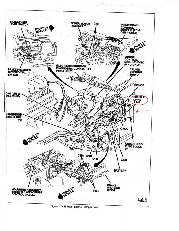
I just love the block car diagram in the FSM showing where the chassis grounding points are located. Not real helpful, IMHO. Anyone have advice or pix showing where those chassis grounds really are? Or suggestions for which one(s) I should check first?
I was thinking to run temporary “jumper” ground wires to the two ground circuits feeding the CCM (CCM connector positions C1 & E16; the inbound grounds, not the switched outbound grounds). This would just be to see if this clears the no-start, an attempt to confirm the CCM is working properly.
Even if it works, it’s not a permanent solution. The AC being stuck on drains the battery in ~60 minutes. Of course, grounding the CCM might also ground and shut off the AC… :O)
Thanks in advance for everyone’s help.
Last edited:

