Welcome to the Corvette Forums at the Corvette Action Center!

Question: C4 Suspension Swap in 65 Mustang

Fbconvert

Member
Joined
Nov 4, 2010
Messages
6
Location
Idaho
Corvette
I own the front a rear suspension of a 1991 c4
I recently purchased a C4 Suspension, front and rear that I am trying to swap in my 65 mustang. Since this is my first post I feel it is probably important for me to introduce my project so you all can have a better understanding.

I am building a car that is comfortable enough that my wife and I can take on road trips (Interior - yes, Roll cage- no) yet sporty enough that I can still have fun with it on the weekends, maybe even enter a few local auto cross events. However, its primary task will be commuting me to work in the summer (26 miles one way). I am an armature, this might be a mistake to mention this but the sportiest car I have ever owned was a 1995 vr6 Jetta, however I am very passionate about my mustang and even though I have never drove it (other than when it was being towed by my truck - which was a blast by the way.) I can not wait until the day I can really stretch her legs. Judging by what all my friends say who are big into racing it's an addiction that can not be tame. So today, what I have listed are my goals but in reality goals change so that's the best I can do for now.

What I need help with in this forum are some technical details about the C4 suspension. I have a lot of question but I will just start with this one for now which has to do with suspension geometries and angles.

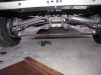
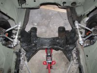
I got the car at about the ride height that I want. I would like some input on the half shaft angle in this picture.

IMG_1217.jpg

Are they too flat? It might be hard to see in this next picture, but the batwing is maybe an RCH wider than the frame rails from the outside edge.
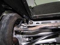
IMG_1218.jpg

If I want to raise that batwing up, thus increase my half shaft angle, I see two option either notch the frame rail and reinforce it, or ask my friend who is a certified welder and can do aluminum, to help me narrow the batwing so that it fits on the inside of the frame rail. Can anyone tell me what the stock half shaft angle is on a C4 corvette? A picture would be sweet.

That's it for now, I got many-many more questions but I hear the only way to eat an elephant is one bite at a time. Thanks in advance for your help.

-FB
 
I recently purchased a C4 Suspension, front and rear that I am trying to swap in my 65 mustang. Since this is my first post I feel it is probably important for me to introduce my project so you all can have a better understanding.

I am building a car that is comfortable enough that my wife and I can take on road trips (Interior - yes, Roll cage- no) yet sporty enough that I can still have fun with it on the weekends, maybe even enter a few local auto cross events. However, its primary task will be commuting me to work in the summer (26 miles one way). I am an armature, this might be a mistake to mention this but the sportiest car I have ever owned was a 1995 vr6 Jetta, however I am very passionate about my mustang and even though I have never drove it (other than when it was being towed by my truck - which was a blast by the way.) I can not wait until the day I can really stretch her legs. Judging by what all my friends say who are big into racing it's an addiction that can not be tame. So today, what I have listed are my goals but in reality goals change so that's the best I can do for now.

What I need help with in this forum are some technical details about the C4 suspension. I have a lot of question but I will just start with this one for now which has to do with suspension geometries and angles.

I got the car at about the ride height that I want. I would like some input on the half shaft angle in this picture.

View attachment 1457

Are they too flat? It might be hard to see in this next picture, but the batwing is maybe an RCH wider than the frame rails from the outside edge.

View attachment 1458

If I want to raise that batwing up, thus increase my half shaft angle, I see two option either notch the frame rail and reinforce it, or ask my friend who is a certified welder and can do aluminum, to help me narrow the batwing so that it fits on the inside of the frame rail. Can anyone tell me what the stock half shaft angle is on a C4 corvette? A picture would be sweet.

That's it for now, I got many-many more questions but I hear the only way to eat an elephant is one bite at a time. Thanks in advance for your help.

-FB

The obvious problem is that the batwing fits wayyyyyy inside a Corvette frame rail, up and against the rear deck and not actually on the rail. Its up between the rails, not on them. The rear rail sections on the vette are more to attach body and accessories than for suspension mounting. In fact, the tail-rails are bolt-on extensions that are sold seperately for wreck repair.They also have a bend/arc upward to allow for more room in the suspension. Your frame rails are parrallel rails from front to back pretty much...whole different animal.
You have a frame thats several inches narrower on each side. The batwing is not the final deciding factor in the ride height, but its part of it. The wheels will hang the same way no matter where or how the batwing is mounted, so there is another problem here.

Have you installed the composite spring? that also determines how the suspension finds its normal resting position. You need a spring thats fairly soft, so there is plenty of arc. The car does not sit on the wheels, the wheels are pushed out of the suspension by the spring and the final ride height is set there. The spring arc and the length of the end link bolts sets the suspension travel and resting height. Tightening the end link nuts drives the body up, off the wheels. Loosening allows the body to drop or settle down on the wheels.
Think..."independent" suspension. Its not part of the frame as most suspensions are, its a totally seperate independent section of the car. I'm curious about how the control struts are mounted....This is a 5 pt suspension and has to be mounted as a 5 pt. The attaching points for the struts and control rods also determines where and how the rear end works, and its resting height.

My best advice, go find a C4 and get under it and study the relationship between the various mounts, where and how they are situated, and how they should work.

PS..
dont think about cutting that batwing...the lattice design is engineered and the addition or loss of any of the triangled cavities will redistribute the stress in unpredictable ways...it'll break.
 
Here is a picture with the spring attached...

IRS.jpg

You can see the car sits much higher but keep in mind it is still just a shell I can pick it up off the ground by my self. I had intended to purchase longer bolts if need be to adjust the final ride height. I understand what you are saying though. in my previous picture that is how the suspension sits at the desired ride height. As far as the control struts (dog bone I like to call them) I will have to cut into my floor pan a little I suspect but the frame rail is very wide or deep I guess at that point so I will have some rock solid anchor to mount them too. I have the bolt on bracket from the suspension that mounts to the actual frame of the corvette. I was planing on mounting it to the frame rail of the mustang, but I am pretty sure it will require some cutting into the floor pan to get the right geometry, which doesn't bother me yet.

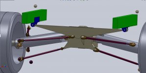
Here a quick conception of what I would like to do.

Frame Mount.jpg

the bracket I can make is in blue the frame rail is green. the model is rough but it should work as an illustration.
 
First off, I think this is a very interesting project. You could have gone with a 03-04 Cobra setup but instead choose a C4 5-link, different. I think that your (nice AUTOCAD drawing) idea will work because in the C4 the differental assembly supports the spring, toe links, lower control arms, and the half shafts. You will still need to have the smaller control links that go from the body to the knuckle. Proper positioning of all of this is key to keep the geometry in some degree of tolerance to design. The only problem I see is that you will not have the C-beam the way the C4's do. The C-Beam supports the back of the transmission and connects the trans. and diff. in one assembly. That being said, I think the problem is not in supporting your tranny or diff. for that matter but when you apply power to the diff. from the drive shaft the front of the diff. housing will want to rise up just like in a traditional solid axle leaf spring car. The leaf fights this to some extent, but you do have this setup. I DO NOT KNOW if your mounts will be able to handle this twisting force place upon them by the drivetrain??? I think that will be the biggest trouble with what you want to do. You may not even have a problem but I see it as a potential one because of the differences in drivetrain and suspension setup.

Hopefully, this makes sense. I do not know how many suspensions or chassis you have constructed or your experience with them. I would find someone with lots of either and get their help or input. Even if you do have a good bit of experience I would do this anyway. No one can think of everything and it always helps to have others thinking about it too.

Personally, you have my respect for taking on a project of this sort. I would not have clue as to where to mount the suspension to keep everything on the up and up. I could figure it out, but it maybe costly, messy, and even painful. I am no engineer, I just try my best to fix'em and modify what I know. I'll leave major suspension and chassis modifications to the pros that know. :)

Just a thought, but does your screen name mean like Fox Body Convert or something like that???

Nothing wrong with a 95 Jetta VR6, I work with a guy that has one. Good for what it is, he has it slammed to the ground, less ground clearance than my 93 C4. Very, very low, he parked it next to my Corvette on day, and I made fun of him (good natured) that even though his car is lowered and has less ground clearance, my overall height is still WAY lower.
 
Thanks for the input. I am actually doing this build a long side a friend who is putting the irs in a Dotson roadster. Believe me no one knows pain like he does when it comes to this kind of thing. He had to narrow the whole thing by a foot or more. him=> :rotfl Me=> :crazy

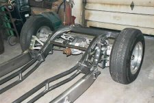
anyways I found this picture after reading your comment. This frame is probably the best model I have seen which describes what my intentions are. Although this uses coilovers which I am not sold on just yet. I really like the mono leaf set up.

Fe3c.jpg

One reason for going this rout is because I think the c4 suspension is probably one of the coolest I have seen. I really like that it is mostly aluminum. Not to mention I have seen people put a cobra irs in a classic and it looked hard compared to this. I will post some more pictures a little later but the width is just about perfect with a 40mm offset wheel and tasteful fender flares.

Proper positioning of all of this is key to keep the geometry in some degree of tolerance to design.

That is what I am concerned about. I would really like to get a close look at a corvette and take lots of pictures of it and dimensions. I am going to try and put something on craigslist just to see if I get any hits. I really like posting on forums too because it is like a second opinion and I really want to do this right.

As for the name it actually stand for fastback convert. my project really began last year when a friend of a friend was tired of his 65 coupe and wanted to just get rid of it. I got wind of it and so he gave it to me straight across. Didn't plan on doing much more then just getting it to run and puting a few cans of spray paint on it. Then I found a fastback roof for sale on craigslist and the rest is history. Thats not really what this forum is about but I will post some pictures of it when I get back on my home computer.
 
Here is a picture with the spring attached...

View attachment 1459

You can see the car sits much higher but keep in mind it is still just a shell I can pick it up off the ground by my self. I had intended to purchase longer bolts if need be to adjust the final ride height. I understand what you are saying though. in my previous picture that is how the suspension sits at the desired ride height. As far as the control struts (dog bone I like to call them) I will have to cut into my floor pan a little I suspect but the frame rail is very wide or deep I guess at that point so I will have some rock solid anchor to mount them too. I have the bolt on bracket from the suspension that mounts to the actual frame of the corvette. I was planing on mounting it to the frame rail of the mustang, but I am pretty sure it will require some cutting into the floor pan to get the right geometry, which doesn't bother me yet.

Here a quick conception of what I would like to do.

View attachment 1460

the bracket I can make is in blue the frame rail is green. the model is rough but it should work as an illustration.

Well, with the spring in place it looks to be typical, but the fact that its not loaded concerns me a bit. The loading with normal weight will cause the suspension to absorb lots of the travel. The counter measure is a stiffer spring, but the composite springs get flatter with higher or faster spring rates. Normal rate for a base vette is around 220 lbs/in with the more aggressive rate for track or street sport being almost 500 lbs/in. (as flexable as an I-beam).
The base spring has a nice long arc, similar to what you have, and the HD Z-51 track spring is almost flat. I am the unfortunate owner of one of those things....and drive my car daily. Its not someplace you want to go...trust me.

So, knowing that you will loose travel with normal loads, and seeing that spring installed and things appear to be about normal, I'd say the only alternative would be to adjust the mounting position relative to the frame. I can tell you that jacking a C4 allows LOTS of drop from the wheels. The suspension tries to compress when the load returns, but the wheels will be way off camber until the car is actually driven and the suspension finds its normal loaded position again.

Tomorrow I will crawl under and get an est difference between the batwing mount opposed to the approx frame line. I know its up at least a couple-3 inches, but I'd like to give you a more accurate guess...

I agree with Rubie, that the center beam is an issue as well. The system all works together and the Corvette rear shell is the frame, so the dog bones are attached to something solid and the beam is the section that adds support and helps transmit torque to the wheels thru the suspension but not absorbed by the suspension. I guess the point being is that the Batwing IS the frame, not part of the suspension.
I wonder how well the frame rails would tolerate the twisting...? No worries, there has to be a way. I've seen Corvette suspension under everything from a pick up to a Gremlin.

What you may want to look into now, before going too far, is some method of cross bracing the frame rails (and support for the bones)in the rear area to provide the required stiffness. Because the batwing carries all the load of the drivetrain and suspension, it has to be secure. That center beam has a lot to do with that. I have felt the difference in a car with a loose beam and it does make a difference, just with bolts that were not torqued, they don't have to be sloppy loose to be a problem. The beam also keeps the alignment and positioning of the batwing/trans constant so there is no change that would effect the suspension. The Key here is the ability to transmit power without loosing any to the frame deflection. Thats what the 5pt link system is all about.

I'll look at that mount tomorrow and let you know how far up there it is in relationship to the frames approx rail position. I will also see if I can locate a chart that i have that has the various rear spring codes and rates so you can see what you have and est what you might need. 90% of this will be in the batwing mounts and strut (bone) geometry.

I certainly admire the challenge. :thumb
 
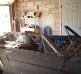
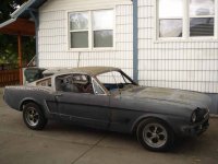
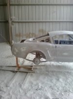
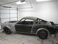
Here are some pictures of the build so far.

The day I got it.

DSC03117.JPG

Cutting the roof off

DSC03188.JPG

Putting the new one on.

DSC03203.JPG

after sandblasting.

Untitled.jpg

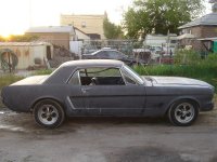
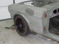
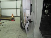
Here is how she is sitting today on the c4 suspension

IMG_1187.jpg

IMG_1180.jpg

IMG_1184.jpg
front side profile

IMG_1173.jpg
 
Wow Boom that would be awesome I look forward to seeing that. Thanks in advance.
 
What a fascinating project you've undertaken! Very cool, sir!!

-Mac
 
Wow Boom that would be awesome I look forward to seeing that. Thanks in advance.

Ok,

I did'nt get a chance to explore too much, as more detail will require taking a wheel off (which has to be done next week for a caliper seal) but I was able to get underneath to refresh my memory a little...
My description of the batwing mounts was not very accurate...

let me try again.
Visualize 2 frame rails that gently sweep outwards as they pass the rear axle area...these are extensions to the frame rails. Sitting between the rail/tail extensions is a box. The batwing mounts are just outboard of this box that drops down by about 3" somewhat lower than the rails....the mounts sit just outside that, on the underside of the tail-rail as it sweeps outward and up from the rear of the cabin area. Just aft of the batwing mount is a lateral brace that runs across the far end of the box. The rails then each go from a box section to a broad Y where the rear facad, bumper and tank all mount.

So, the batwing mount is almost sandwiched between the box and the rail extensions. Its difficult to see the curve of the rails, but they obviously go upward to accept the rather tall rear suspension assembly, batwing included.
The mounts are welded at the base, to the frame rail, with the box reinforcing the rails.

I have to rebuild a caliper next week, so a rear wheel has to come off and I know there is much more detail to be seen thru the wheel well. I'll get some pics and post them so you can see the detail for yourself. A verbal description is almost impossible without some reference.
Hope this helps.
 
What a fascinating project you've undertaken! Very cool, sir!!

-Mac
I'm with Mac - interesting project! Your decision to change the roof was a mystery to me, but seeing the before and after photos helped. I like the fastbast design too.

Good luck with your project!
:wJane Ann
 
Thanks for the positive feedback.

I got this response from another forum I am on and I am just wondering if anyone has had any experience with it.

The c4 IRS while not as advanced as the newer dual a-arm setups will work fine, although if you have the budget the DRM pieces do make an improvement, although I wonder since you have freedom for the front dog bone pickups if you can accomplish the same anti-squat increase just by putting them in the right place. I believe they sell 2 or 3 different pieces that change the geometry. The anti-squat kit might just be a bracket that bolts in to change the dog bones so again, you can just design that in. But they also make some kind of bump steer change to the upright too, go check out their website. I agree the half shafts should be more or less level at ride height.
Has anyone used the kit from DRM?

Here is one thing that I found http://dougrippie.com/?p=1272. But like the quote says I have the freedom to change geometries I just need to know what they are.

Thanks for the help,

-FB
 
. Because the batwing carries all the load of the drivetrain and suspension, it has to be secure. That center beam has a lot to do with that. The beam also keeps the alignment and positioning of the batwing/trans constant so there is no change that would effect the suspension. The Key here is the ability to transmit power without loosing any to the frame deflection.
Front support for diff head usual method in retro fits.Same as most cars with IRS.
C4 is one of the few IRS cars to have a beam from trans to diff

56rear1.jpg

6A.jpg
 
vettoz.....that is one cool looking frame and suspension. What kind of body will be going on that? They look like mustang wheels.
 
vettoz.....that is one cool looking frame and suspension. What kind of body will be going on that? They look like mustang wheels.
Custom chassis for a '56 Chev ( can't find link to maker )
Some stupid price like 30K for rolling chassis with all polished parts

56side2.jpg

56front1.jpg


Newman Creations do something similar but they use a custom C beam and a extra cast alum bracket to mount it to which seem rather a waste

55-57 Chevy with C-4 Corvette suspension
 

Corvette Forums

Not a member of the Corvette Action Center?  Join now!  It's free!

Help support the Corvette Action Center!

Supporting Vendors

Dealers:

MacMulkin Chevrolet - The Second Largest Corvette Dealer in the Country!

Advertise with the Corvette Action Center!

Double Your Chances!

Our Partners

Back
Top Bottom