Welcome to the Corvette Forums at the Corvette Action Center!

Help! Module 1 C41 Module 4 Err Module 9 H72

When I jump pins A & B together on the ALDL the SES light does not flash just stays solid and fans do come on also. The odometer is the same as they asked for the mileage when it was rebuilt. Thanks
 
When I jump pins A & B together on the ALDL the SES light does not flash just stays solid and fans do come on also. The odometer is the same as they asked for the mileage when it was rebuilt. Thanks


Did you reinstall the original little circuit board with the eprom on it in the repaired ECM?
That contains the engine calibration information.
 
yes I did and double checked it and it is seated properly.

If no 12 flashes, the ECM has failed it's self test. It should also energize the IAC valve which makes a clicking noise.

Only thing you can do is verify the 12 volts and grounds used by the ECM are connected.

Do you have a volt meter that you can measure the voltages at the ECM connectors?

If you do I can tell you what wires to check if the color of the wires are the same for a 93 as your 92.
 
*******************************************************************************
I'm looking at the schematics for a 93 which uses the same ECM as a 92. I don't know if the color of
the wiring is the same but the pin outs should be the same.

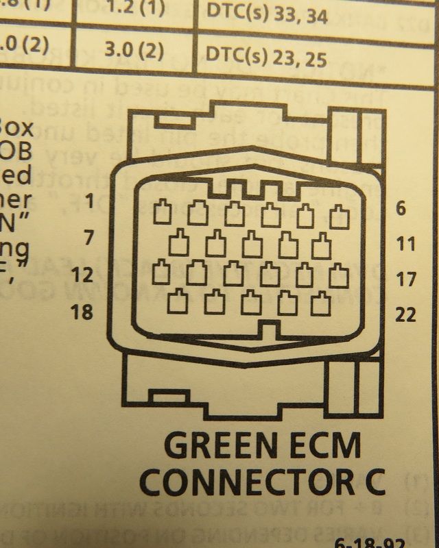
Here's what the pin outs look like if you were to look into the ECM connector.


Disconnect the Red and Green connectors at the ECM .
With your Red meter lead probe the connector pins of the disconnected connectors.

The connectors are 22 pins and the pin #'s should be labeled.

**************************************************************************************
Set the meter to read resistance. Connect the Black meter lead to the negative battery terminal for both tests.
**************************************************************************************

These wires should have zero ohms to the negative battery terminal.

Red 22 pin connector

pin 6 Tan/White wire is a ground wire
pin 17 Black/White wire is a ground wire
pin 22 Black/White wire is a ground wire


Green 22 pin connector
pin 9 Pink/Black is a ground wire


*********************************
Set meter to read DC volts
*********************************

These wires should have 12 volts on them.

Green 22 pin connector

pin 6 Orange wire hot all the time
pin 12 Pink/Black wire hot with ignition On
pin 17 Orange wire hot all the time
pin 18 Yellow wire hot when ignition is On
 
Last edited by a moderator:
OK here are the results.

Resistance Readings

Red 22 Pin Connector
PIN 6 1.6 Ohms
PIN 17 1.6 Ohms
PIN 22 1.6 Ohms

Green 22 Pin Connector
PIN 9 Open no reading

Voltage Readings

Green 22 Pin Connector
PIN 6 12v always
PIN 12 12n Ignition On
PIN 17 12v always
PIN 18 no volts

Maybe Finally onto something ?


I don't think those two wires are the problem.

Those two wires are 12 volts for the Optispark and reference ground for the Optispark.

I know the 92 had a different plug at the Optispark than a 93. I believe it had 5 wires at the Optispark something about an extra ground that they eliminated in 93.

Can you unplug the connector at the Optispark and tell me the color of the wires and if the connector plug
is labeled with pin numbers such as A B C D E?
 
Yes they are

A BLK/RED
B PPL/WHT
C YELL
D BLK/PNK
E
F Solid Copper Wire

The Opti-Sark Connector has 4 wires coming out of it these were taken from the secondary harness connector on top of the intake manifold. Not sure where the solid wire comes in as there is only 4 wires out of the Opti-Spark Connector.
 
Last edited:
Yes they are

A BLK/RED
B PPL/WHT
C YELL
D BLK/PNK
E
F Solid Copper Wire

The Opti-Sark Connector has 4 wires coming out of it these were taken from the secondary harness connector on top of the intake manifold. Not sure where the solid wire comes in as there is only 4 wires out of the Opti-Spark Connector.


Well you need to reconnect the connectors at the ECM.

The ECM is what supplies the 12 volts to the Optispark.

With the ignition On and volt meter set to DC volts.

At the pig tail connector I believe you're talking about see if you can back probe the connector.
If you can't back probe the connector disconnect it and measure the wires of the connector plug
going back towards the ECM.

Red probe on Yellow wire.
Black probe on Black/Pink wire
You should measure 12 volts.

Do not short out any pins. :chuckle
 
So do you want me to go between the optispark connector and the ECM Connector ? And just the yellow wire ? Or are any other readings needed ?
 
At the connector if I probe the BLK/PNK with the black lead and probe the Yellow wire with the red lead I get 12 volts/Battery voltage. This is with the connector unplugged.
 
So do you want me to go between the optispark connector and the ECM Connector ? And just the yellow wire ? Or are any other readings needed ?

The Yellow wire is 12 volts to power the Optispark.
The Black/Pink is the ground ref from the ECM to the Optispark.

This is not causing your ECM problem so not important at the moment. ;)


What bothers me is the 1.6 ohms you're reading which is pretty high.
When you short your meter leads together do you read zero ohms?

From the negative battery cable one end bolts to the engine block around the oil filter area.
Another ground wire from the negative battery terminal goes to the frame.
A braided wire below the battery area goes from the frame to one of the driver side
bell housing stud.

When you have time, remove the cables and clean the surface and see if you can get the resistance
below an ohm.

If that doesn't get the ECM blinking code 12 when you short Pin A to Pin B, the ECM must be defective.

The 92 cars seem to have a high ECM failure rate. Appears to be bad flow soldering. Some people have pounded on the cover and it starts to work. Flakey solder joints.
 
Last edited by a moderator:
Should be able to do that tommrow and will run the tests again and post the results. Thanks a lot.
 
Okay I cleaned everything and the most I am seeing is 0.01 to 0.00 ohms on the grounds. Still wont flash codes I have 2 ECM,s tried both with same result.
What about the PROM/MEMCAL would that have any bearing on it ? Also when you first hook up the battery it will fire off for about 2 seconds and then it will do it again and after that just cranks and cranks.
 
Last edited:
Okay I cleaned everything and the most I am seeing is 0.01 to 0.00 ohms on the grounds. Still wont flash codes I have 2 ECM,s tried both with same result.
What about the PROM/MEMCAL would that have any bearing on it ? Also when you first hook up the battery it will fire off for about 2 seconds and then it will do it again and after that just cranks and cranks.


If you don't short pin a to pin b.
When you turn the ignition On can you hear the fuel pump prime for two seconds?
Are the radiator fans running?

If you disconnect the negative battery terminal and remove the memcal.
Reinstall the negative battery terminal and turn the ignition On what are the symptoms?

Reinstall the memcal.
Service manual says disconnect the Gray connector.
Turn the ignition On is the Service Engine Soon indicator On?
If it's On something is wrong with the Service Engine soon indicator circuit.
 
Last edited by a moderator:

Corvette Forums

Not a member of the Corvette Action Center?  Join now!  It's free!

Help support the Corvette Action Center!

Supporting Vendors

Dealers:

MacMulkin Chevrolet - The Second Largest Corvette Dealer in the Country!

Advertise with the Corvette Action Center!

Double Your Chances!

Our Partners

Back
Top Bottom