Welcome to the Corvette Forums at the Corvette Action Center!

Who Here Is The 1981 TH350c (wiring) EXPERT ?

HammerDown

Well-known member
Joined
Jan 23, 2003
Messages
474
Location
Glenolden Pa
Corvette
1981 White/ Red int.
Just finished rebuilding my 1981 TH350c

Before I install it back in the car, I noticed the outside plug that connects to the transmission has 3-wires > however, one of those three connect to nothing!
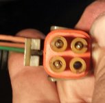
Outside Plud with wires.jpg


Note the case socket...(only two connectors)
Inside the trans pan, the lock-up solenoid is a 'two-wire' thus only two connect to the backside of the blue case-socket.
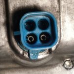
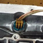
case socket.jpg
inside Plug.jpg


Below is my lock-up solenoid and inside wiring...those two plugs connect to a pressure switch, that does bench test with air.
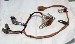
TCC solenoid.jpg

Here's the thing > since having my car 'new', I cant' say I've ever noticed the RPM dropping at highway speeds...almost like the lock-up never really functioned as should.

And, seeing a three-wire plug, and noticing only 'two-wires' actually connect to inside the trans has me thinking...was it wired wrong from the factory?

Does anything above appear to be wrong, is there any way I can test the three-wire plug to make sure it's doing what it should?

Thanks for any info.
 
Last edited:
Circuit diagram shows exactly what you have, a three pin plug connected to a two wire solenoid.
may just be the way it looks in the pic, but do the pins line up when you plug the outside plug into the case socket?
 
Last edited:
Circuit diagram shows exactly what you have, a three pin plug connected to a two wire solenoid.
may just be the way it looks in the pic, but do the pins line up when you plug the outside plug into the case socket?
Thanks for the reply...so you have a wiring schematic for our 81...that's great!
Yes, the outside plug fits blue socket nicely.
May I ask, does you wiring diagram show any color codes for the wires?
Would be nice to confirm the plug colors going to the correct location.

Then my next thing is to locate a vacuum switch and brake switch...I believe those two mentioned items are also in the operation.
Thanks again, Ray
 
I found our the exact same thing a few years ago. I don't remember if the wire goes all the way to the ECM, i think it is connected to ground if i remember correctly. You can connect a 700 to it without changing anything. On 700r4's the extra wire is used to trigger high gear. But i need to look it up to be sure!

Greetings Peter
Hi Peter, local transmission shop tried to sell me a 700r4 for $2000! (heck with that)
And while it will bolt to my engine the cross-member has to be different or modified and the drive shaft must be shortened...and the 700r4 uses some 35hp just to turn it...all three reasons make me not interested!

Before I reinstall my TH350c, I just want to check what the (2) out of (3) wires do, the correct color codes, why the 3'rd wire does nothing, and how to test the wires going into the transmission to make sure everything outside the trans is working properly.
 
Thanks for the reply...so you have a wiring schematic for our 81...that's great!
Yes, the outside plug fits blue socket nicely.
May I ask, does you wiring diagram show any color codes for the wires?
Would be nice to confirm the plug colors going to the correct location.
Diagram shows them as pink/black (hot in start, run), Dark green/white (High gear input to ECM), Tan/Black (ground for EGR bleed control and TCC Via relay back to ECM) hope that makes sense. Diagram appears to show the dark green/white as unused. Have noticed something a bit odd on the diagram; the TCC solenoid is a slightly different symbol to all the other solenoids. this may not mean anything though.

Then my next thing is to locate a vacuum switch and brake switch...I believe those two mentioned items are also in the operation.
Thanks again, Ray
brake switch is shown in the dash harness; wire colors are purple, pink/black.
 
Diagram shows them as pink/black (hot in start, run), Dark green/white (High gear input to ECM), Tan/Black (ground for EGR bleed control and TCC Via relay back to ECM) hope that makes sense. Diagram appears to show the dark green/white as unused. Have noticed something a bit odd on the diagram; the TCC solenoid is a slightly different symbol to all the other solenoids. this may not mean anything though.


brake switch is shown in the dash harness; wire colors are purple, pink/black.
Thanks for that Ant :thumb

this is what it 'looks like' I have...
* green w/white stripe
* orange w/black stripe
* brown w/ black stripe

My colors may be faded...maybe my orange w/black stripe is really 'pink/black' and my brown/black may actually be 'tan/black'?
Green/white not used...good to know!

Can you please check one more thing?

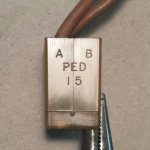
The below inner two-wire plug is actually stamped A & B and on the back C & D
Two of those outside 3-wires connect to (A) & (D)
Does your schematic show which wires either 'pink/black' or 'tan/black' goes to A and D ???
This will help me confirm my three wire plug is factory-correct!
inner trany plug.jpg
 
Last edited:
Peter's correct A and D.
I agree with you on your guess of the faded colors. Pink on mine is now more of an orange and tan is brown.
 
Thanks fellas, it appears the correct two color-coded wires are going to their proper holes to the outside plug and then inside is two tan wires (one striped) going to the + solenoid and the other wire is going to one side of the pressure switch.

So, with that I'll get my transmission back in and then check out the brake switch and I still need to locate the vacuum switch, and test that.
Again, thanks for your time and effort :beer
 
Hammer,

did your transmission valve body had one or two pressure switches?

The wired it for second and third gear to lock up. Mine had that extra wire for the additional lockup.

20140405_052540835_iOS.jpg
 
GerryLP, thanks for the reply and info.
my valve body only has one pressure switch.
In my above pics the two Plastic Tan plugs CONNECT to It's leads.
Pressure switches are color coded, mine is silver. Bench tested it with a meter and compressed air and it's circuit closed so I guess it's ok.
 
GerryLP, thanks for the reply and info.
my valve body only has one pressure switch.
In my above pics the two Plastic Tan plugs CONNECT to It's leads.
Pressure switches are color coded, mine is silver. Bench tested it with a meter and compressed air and it's circuit closed so I guess it's ok.

I'll look to see if I still have images of my transmission's wiring, but the two tangs you have are supposed to be one per pressure switch. The switch itself grounds to the valve housing and completes the circuit. If you look at the shop manual's page 7A3-15, figure 7A3-36, lower right-side configuration shows the closest configuration my transmission had; however, the solenoid in my transmission was weak (the transmission behaved like a manual transmission does when you let the clutch pedal out at low speeds-like when you drive at 20 MPH on a manual transmission car and put it in third gear). Anyway, I could not find a replacement 3-wire solenoid. I called vendors ahead of time and asked the question, and they would check their items, and report back that it was a 2-wire solenoid. So after all the searching, I opted to buy a 2-wire type, and moved the third wire to the new one from the old one.
 
Last edited:
Garry, if I understand you correctly you're saying each one of my Grey connectors should go to (2) separate pressure switches that each have one terminal???

Thing is, my valve body only has a spot for (1) pressure switch and the switch has two terminals.
I believe my lu solenoid is NOT self grounding, as when I tested the negative wire coming out of it, to its own case it's not a closed circuit.
Bench testing my pressure switch with a meter, until air pressure is put to it, it is an open circuit...add some air-psi and it closes, making contact between its (2) terminals.
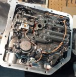
Below is a pic as I began tearing my TH350c down.
I don't have a GM service manual...thus why I was reaching out for someone here that does ;)
valve body.jpg
 
Last edited:
Garry, if I understand you correctly you're saying each one of my Grey connectors should go to (2) separate pressure switches that each having one terminal???

Thing is, my valve body only has a spot for (1) pressure switch and the switch has two terminals.
Below is a pic as I began tearing my TH350c down.
I don't have a GM service manual...thus why I was reaching out for someone here that does ;)
View attachment 18322

do you see that plug to the right (on the image) to the pressure sensor? That's where the other one goes. However, I am not sure if both are rated to the same pressure. I am still searching my photos for the image of my transmission.
 
do you see that plug to the right (on the image) to the pressure sensor? That's where the other one goes. However, I am not sure if both are rated to the same pressure. I am still searching my photos for the image of my transmission.

Ahhh, yes I notice it now.

What 'I' may have is a very limited set up because it was used for a short while just before they went to 700r4's. That's why I have the extra wire, I believe my car is set up for 700. (no second) gov(psi) switch as I mentioned because it's completely computer controlled. So "a" lead (should say on side of the plastic connectors ) is power, through that single psi switch in my valve body, then the computer grounds it to complete the circuit...make sense???
What year was your vette again?
 
Last edited:
Ahhh, yes I notice it now.What 'I' may have is a very limited set up because it was used for a short while just before they went to 700r4's. That's why I have the extra wire, I believe my car is set up for 700. (no second) gov(psi) switch as I mentioned because it's completely computer controlled. So "a" lead (should say on side of the plastic connectors ) is power, through that single psi switch in my valve body, then the computer grounds it to complete the circuit...make sense???What year was your vette again?
Hammer,I have an L81. Going from memory alone (warning!!! lol :L ), the black wire went to one post of the pressure switch, a shorter white wire went from the remaining post to the other pressure switch post, and the other long wire went to the remaining post on the second pressure switch. I believe that the thrid gear lock-up has to be separate, so that the computer can control it on decelaration and other driving regimes.
 
Ahhh, yes I notice it now.

What 'I' may have is a very limited set up because it was used for a short while just before they went to 700r4's. That's why I have the extra wire, I believe my car is set up for 700. (no second) gov(psi) switch as I mentioned because it's completely computer controlled. So "a" lead (should say on side of the plastic connectors ) is power, through that single psi switch in my valve body, then the computer grounds it to complete the circuit...make sense???
What year was your vette again?
Very close the computer grounds a relay which connects the solenoid to ground. The brake switch stops this relay from switching when braking. (thus no lock up during braking)
Your Vette is St. Louis assembled right? Seems unlikely that they would have changed the wiring during the year it was shut down.
Seems odd that Gerry (Also A St. Louis Vette) has a different configuration for his wiring though. (Assuming his memory is right)
 

Corvette Forums

Not a member of the Corvette Action Center?  Join now!  It's free!

Help support the Corvette Action Center!

Supporting Vendors

Dealers:

MacMulkin Chevrolet - The Second Largest Corvette Dealer in the Country!

Advertise with the Corvette Action Center!

Double Your Chances!

Our Partners

Back
Top Bottom