Welcome to the Corvette Forums at the Corvette Action Center!

1992 Lt1 vacuum help!

daved2

Member
Joined
May 7, 2014
Messages
19
Location
sierra vista arizona
Corvette
1992
I just picked up a 1992 LT1 and all the vacuum lines and engine were in boxes. I got everything straightened out but the vacuum lines. I am wondering where the main line that feeds the vacuum tank comes from? I have the vacuum lines on the drivers side and the line coming off the cruise control and it has a T fitting on it, I also have a line coming out of the wiring harness under the brake booster. What I need to know is does that line coming out of the wiring harness feed vacuum to the tank and cruise control? I know the lines on the driver side of the engine go to the EGR then T off at the manifold and go to the ASR module and stop there or does it go to the tank or cruise control?
I'm thinking with the connections I see there that the line coming out of the wiring harness near the booster feeds vacuum from the other side of the manifold where there are two vacuum lines coming out of the wiring harness that go to the passenger side manifold and both of them feed off of the manifold with a check valve from the lower port or one of the two ports on that side of the manifold and the other one there just feeds the fuel pressure regulator, Am I correct?
Or does that line on the driver side go to the EGR then the manifold then the ASR then the tank and cruise control?
So basically I have three vacuum lines coming out of the wiring harness near the firewall, two on the driver side and one on the passenger side below the brake booster and don't know how the hook to the tank, or where the tank actually gets it's vacuum from?

Thanks guys!
Any help would be appreciated.
 
Welcome to the Corvette Action Center.

I'm going to move your thread into the C4 Tech forum for greater exposure...
 
I just noticed an error in my original post, instead of two vacuum lines on the driver side I have two on the passenger side behind the head and one on the driver side coming out of the wiring harness below the booster.

Sorry about that guys!
 
reply

I already looked through that diagram page and can't find one that matches my configuration. I only have one line coming out of my vacuum tank mounted behind the driver headlight. For a vacuum canister to work right it has to have an inlet and outlet hose. So this tank on mine is probably just an indicator of how much vacuum I am getting.
I had a C3 that I did all the vacuum lines on that and have it just about memorized but this thing is different.
What I am thinking is that there are three separate vacuum systems on this engine, which all come from the engine of course.
The right side feeds the cabin and fuel pressure valve, the driver side feeds the EGR and ASR, which make two systems and the third comes off the cabin and goes to the cruise control from the wiring harness behind the brake booster and then goes to the tank,,, that's three the way I see it but there are check valves and no diagrams to show which way the check valves go.
I am trying to find someone to confirm that I am right about how this system works and just about got it, just need confirmation on the driver side check valve and where or which way it goes.

But thanks for your suggestion.
Well Appreciated.
 
Driver Side vacuum lines

I guess there's no one out there with a 92 or 93 to tell me where the vacuum lines go from the ASR module huh?
Or if it is on the same line as the cruise control?
 
I don't have a '92 or '93 for reference, but I so have a 95. ASR (traction control) has no vacuum hoses or lines associated with it as it is electrically operated. There is a throttle cable that connects the ASR adjuster to the cruise control servo and a vacuum hose does connect to that servo but that's as close to ASR as any vacuum gets.

That plastic ball up by the headlight is a vacuum reservoir and, thus, has only one connection. It is part of the cruise control system. Quick summary of the cruise: One hose runs from the servo, into the car and to the cruise release valve(s). The other hose connects to the air valve, manifold vacuum and the reservoir.

My advice is to purchase a copy of the 1992 Factory Service Manual from CAC sponsor Zip Products. In the FSM you will find discussions of all vacuum operated systems along with diagrams of the vacuum hoses and illustrations of components.

Good luck.
 
reply

I worded that wrong, the ASR Traction control is mounted on an EGR component (air divert valve)that has a big hose that goes to the electric air pump in the front by the vacuum canister and the other hose to that valve goes to the Tube on the manifold. So the vacuum line is not part of the ASR but it appears to be until you take a closer look.
So your saying that a vacuum line comes off your cruise, one goes to the release on the gas pedal and the other one goes to the air divert valve and then the tank and then over to the manifold? Or does it hook to that vacuum line coming out of the wiring harness below the brake booster and then to the air tank
I have a service manual but it just shows the cruise control vacuum lines and one goes to the release valve and the other one hooks to a T fitting on the line coming out of the wiring harness and then goes to the tank.
When I look at the EGR vacuum system that is right on the sticker above the radiator it shows the vacuum line going to the EGR valve then T's off at the manifold and goes right to the divert valve.
I just found another vacuum fitting on the air divert valve yesterday when I hooked it up but the book says it is air to atmosphere so I guess no vacuum line hooks to that.
The book describes the big hoses which anyone can figure out where they go in great detail but the vacuum line just says vacuum source on it and doesn't show where the source comes from but I know it is from the driver side manifold.
I guess it would be a lot easier to understand this book if everything was hooked up, but when everything is in a box and you only have pieces the book is not detailed enough to arrange the pieces the right way.It has a better diagram for the J Vin engine but the P engine diagram sucks.

Thank you for taking the time to look at your car for me I really appreciate it.
Thanks again
Dave D
 
Reply

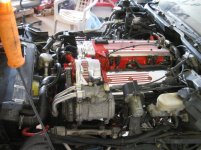
Vette in progress 005.jpg
I should be cranking this engine in the next day or so and I guess I will find out if that line coming out of the wiring harness is the vacuum source as soon as it is started. It's a 92 LT1 as you can see in the pic.
It's been completely rebuilt with all the best parts like forged crank and rods, Probe forged pistons and it's stroked to a 383 with 11/1 compression ratio so it should be pushing 475 HP or better.
The last stroker I built, when I sold it to a guy in Texas he nailed it on his first drive (I delivered it to him from AZ) and then started shifting, we didn't hardly move until he hit third and the front end came off the ground,,, Might sound off the wall but it did, we were on a really rough road and the tires just dug in and all I saw was bright Blue when it came up. That was my 70 Vette, when the speedo hit 145 he let off the gas and shook my hand and said,,NICE CAR!
 
Reply

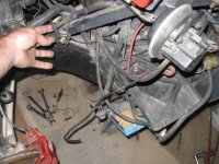
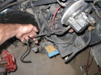
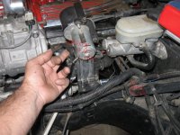
Here are the lines I have, the air valve line goes to the intake I'm pretty sure but the other ones from the cruise and the line coming out of the wiring harness and tank line, do they hook together? And there is a check valve involved here that goes somewhere between the tank and cruise. In the other post above this one the intake T fitting line is broken as well, all that plastic tubing and none of the ends match up.
Does a check valve connect the lines from the cruise to the tank?

Thanks again guys.


Vette vacuum.jpgVette vacuum 001.jpgVette vacuum 003.jpg
 

Corvette Forums

Not a member of the Corvette Action Center?  Join now!  It's free!

Help support the Corvette Action Center!

Supporting Vendors

Dealers:

MacMulkin Chevrolet - The Second Largest Corvette Dealer in the Country!

Advertise with the Corvette Action Center!

Double Your Chances!

Our Partners

Back
Top Bottom