Welcome to the Corvette Forums at the Corvette Action Center!

Doing Your Own Front End Alignment

Status
Not open for further replies.
alignment for late C3

Pretty much referring to C3 here...late models factory specs are better( than the old 70s specs) for sport-street, can be modified for true track. But for C3 , do some we searches..look at quite a few sites that do not just re quote factory..vbandp, Duntov and more..plenty of variations but as you look thru you will find kind of a middle concensus..and that is what I went with for an 81..OK..so here is what specidied FOR THE SHOP to use..individual results may vary..on my car, seems very good. Again, align done after new bush, wheel bearings, ride height at rear with the rear most spring bolts/and good bushes (poly if you like) shocks, etc. A nice add is the adjustable rear camber strut.
Do the rear first: rear camber .5 deg each side. then rear toe 1/16 in each side so 1/8 total (some may like less..1/32 ea). Pivot bolt to 50ft lb. It is a "pivot" and needs to move. Then do front: caster first-right side: 3.0 to 3.25 if it will go to 3.25. Somewhere in there is about max you can get., Ledt side approx .3 deg less than right (allows for crown of roads); Now front camber .29 neg both sides. Then front toe: 1/16" in each side, so total toe is 1/8" in. Subtract shims at front A armbolt to increase positive caster, and or add shims at rear bolt as needed, goal is max pos caster while maintaining toe and camber spec. No more than . 4inch diff in thickness of front front to front rear shim packs. Two threads min showing beyond nut. When front is complete, tighten to firm, back off, then lightly tighten to 15 ft lb the bolt having thinnest shim pack, then the other, then final torque thin first, var on ground, lower inner pivot bolts to 40ftlb, upper to 50 ftlb..with car on ground. Check the shops computer print out of completion for proper spec. Only slight tolerance off spec is permitted due to shim thicknesses. Steering wheel of course must be set dead straight when wheels are dead straight. But fact check me yourself see if you like these late C3 specs. Happy driving..with this set up I have no wander even on uneven or stud tire grooved roads, and dead on stuck to the road cornering,.
Nick
 
I'll get back to you guys around Saturday or Sunday. I'm sorry for the delay but I'm dealing with a big problem right now and just don't feel like taking the time to give you detailed instructions. Please be patient.....................
 
Pretty much referring to C3 here...late models factory specs are better( than the old 70s specs) for sport-street, can be modified for true track. But for C3 , do some we searches..look at quite a few sites that do not just re quote factory..vbandp, Duntov and more..plenty of variations but as you look thru you will find kind of a middle concensus..and that is what I went with for an 81..OK..so here is what specidied FOR THE SHOP to use..individual results may vary..on my car, seems very good. Again, align done after new bush, wheel bearings, ride height at rear with the rear most spring bolts/and good bushes (poly if you like) shocks, etc. A nice add is the adjustable rear camber strut.
Do the rear first: rear camber .5 deg each side. then rear toe 1/16 in each side so 1/8 total (some may like less..1/32 ea). Pivot bolt to 50ft lb. It is a "pivot" and needs to move. Then do front: caster first-right side: 3.0 to 3.25 if it will go to 3.25. Somewhere in there is about max you can get., Ledt side approx .3 deg less than right (allows for crown of roads); Now front camber .29 neg both sides. Then front toe: 1/16" in each side, so total toe is 1/8" in. Subtract shims at front A armbolt to increase positive caster, and or add shims at rear bolt as needed, goal is max pos caster while maintaining toe and camber spec. No more than . 4inch diff in thickness of front front to front rear shim packs. Two threads min showing beyond nut. When front is complete, tighten to firm, back off, then lightly tighten to 15 ft lb the bolt having thinnest shim pack, then the other, then final torque thin first, var on ground, lower inner pivot bolts to 40ftlb, upper to 50 ftlb..with car on ground. Check the shops computer print out of completion for proper spec. Only slight tolerance off spec is permitted due to shim thicknesses. Steering wheel of course must be set dead straight when wheels are dead straight. But fact check me yourself see if you like these late C3 specs. Happy driving..with this set up I have no wander even on uneven or stud tire grooved roads, and dead on stuck to the road cornering,.
Nick

I tried do do my own alignment a couple of times with a "Dunlop" camber gauge, strings between jackstands and a tape measure. I could do camber and toe, but not caster because I didn't have any wheel plates. With those limitations, it worked well, but was quite time consuming. Also, the toe wasn't as accurate as I'd like. A front end shop with a good alignment rack was faster and more accurate. Considering what some alignment shops have, today, trying to do your own front alignment is for the really frugal types, IMO.

I always set up my '71 w:

-0.5° front camber
as much caster as I could get with that camber setting.
1/16-in front toe in
-0.25° rear camber
1/32-in per side, rear toe in.

This was for a front end with offset upper control arm shafts
VBP "Smart Struts" kit in the rear in place of the stock lateral links and mounting
Tires are 275/40ZR17, front, and 315/35ZR17, rear, on C4 ZR-1 replica wheels.

This alignment always worked well and even provided reasonably good tire tread life.

Other suspension mods are:
Front "spread bar" between upper control arm shafts, custom made for use with BBC
Global West front control arm bushings, upper and lower
Moog adj. ball joints on lower arms
HD tire rod and tire rod ends.
1.25-in adjustable front stabilizer bar with spherical bearing links.
Global West rear trailing arms w rubber end bushings
Spherical bearings in lateral link ends
0.75-in adjustable rear stabilizer with spherical bearing links.
 
sounds like a good set up Hib. And I agree, There are some things we used to do ourselves that no longer make sense in light of modern technology.
There are places that will do a "free alignment check" then hoping to get your business when it is found to be out of spec..and it will (often) be out of spec..whether it really is or not is another topic. IF..you have a great relationship with a shop and owner having a computer/laser,4 wheel alignment then maybe one could do own and then get a check.
Just took all the exhaust manifold / spark plug heat shields off..that I can do myself..and it is tedious..with mirrors and tiny tiny bolt head screws you can not see or reach. getting ready to take car to "the man" to remove exhaust manifolds and put the long tube Hooker Headers on..and set up the exhaust..that is a job I will not do myself !!
Nick
 
I'll get back to you guys around Saturday or Sunday. I'm sorry for the delay but I'm dealing with a big problem right now and just don't feel like taking the time to give you detailed instructions. Please be patient.....................
It sounds like you're going through a rough time. I hope you're doing okay?

Although the guys are giving you a bit of razzing, I'm sure they're with me in wishing you a swift recovery.
:w

Mac
 
Electronic Digital Angle Finder

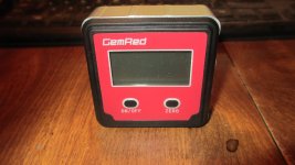
Early this week I bought an electronic digital angle finder for $31 so I used it this morning to align my front end. The last time I aligned it was about 5 years ago (over 100,000 miles) and the caster and camber had changed considerably; like 4 degrees caster and -.9 degrees camber. So I set both sides to 2-1/2 degrees caster and 0 degrees camber. But as I was aligning it I took a lot of pictures so I could show you guys how easy it is to align your own front end using a home made tool and an inexpensive angle finder like the one I just bought. Some time this weekend I'll post the instructions and pictures.
 
Early this week I bought an electronic digital angle finder for $31 so I used it this morning to align my front end. The last time I aligned it was about 5 years ago (over 100,000 miles) and the caster and camber had changed considerably; like 4 degrees caster and -.9 degrees camber. So I set both sides to 2-1/2 degrees caster and 0 degrees camber. But as I was aligning it I took a lot of pictures so I could show you guys how easy it is to align your own front end using a home made tool and an inexpensive angle finder like the one I just bought. Some time this weekend I'll post the instructions and pictures.

So you don't see the need to compensate for crowned roads?
what about the rear alignment? Or do you not think that will change over time?
 
Damned

I gave my detailed instructions with pictures 3 times and each time my computer shut down just before I pushed the SEND button. Each time losing about 30 minutes of work. So I'll try again later.......................
 
Aligning Your Own Front End

Okay, I promised you instructions on how to align your own front end and here it is:

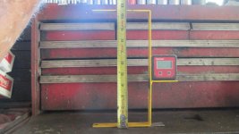
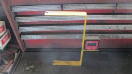
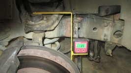
1. First of all you'll need to make a simple tool using 24" of 1/8" X 1" steel flat bar and buy a magnetic base digital angle finder (about $30) as shown in pictures #1 and #2. The tool is 10-1/2" tall and 5-1/2" wide (excluding the 2-1/2" long shelf for the angle finder to sit on) and with 1/4" holes drilled exactly 5" from the angle finder's side.

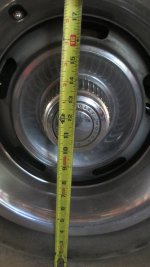
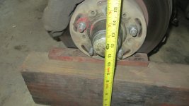
2. Measure the height of the center of your hub cap to the ground and it'll be about 11-1/2" to 11-3/4 (picture #3). I am running 225X60R15 tires and mine measured 11-5/8".

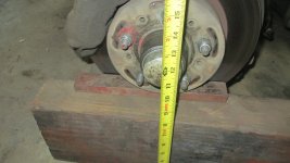
3. Remove the wheel and set the hub onto a 8" thick timber and shims to obtain the same height (picture #4).

4. Hang the tool (and angle finder) onto the upper and lower ball joint grease zerks. The angle finder will display the caster angle of the spindle (picture #5).

5. Adjust the caster angle by adding or removing shims at the rear of the upper control arm (picture #6)

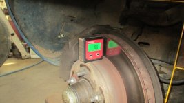
6. Set the angle finder onto the top of the rotor's hub to measure the camber angle (picture #7).

7. Adjust the camber angle by adding or removing shims at the front of the control arm (picture #6 again).

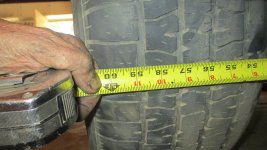
8. To measure the amount of toe in hook a 1" wide tape measure into the REAR inner tread of the opposite tire then measure the distance to the outer tread of the tire on your side (picture #8). Then do the same measurement on the front of the tire and you should have about 1/8" to 1/4" less (picture #9) The rear measurement will show about 58-7/8" and the front measurement will show about 58-5/8".

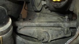
9. Adjust the toe in by turning the left and right tie rods equally about 1/8th turn at a time until the measurement on the front is 1/8" to 1/4" less than the rear (no picture of tie rods but you know where they are).

After uploading my post I see the picture of the front toe in measurement and the picture of the tie rod didn't load so I assume I had reached my maximum file size.


Good luck...................
 

Attachments

  • 1971 Corvette Front End Alignment .jpg
    1971 Corvette Front End Alignment .jpg
    246.9 KB · Views: 124
  • 1971 Corvette Front End Alignment 001 (2).jpg
    1971 Corvette Front End Alignment 001 (2).jpg
    248.8 KB · Views: 115
  • 1971 Corvette Front End Alignment 002.jpg
    1971 Corvette Front End Alignment 002.jpg
    245 KB · Views: 114
  • 1971 Corvette Front End Alignment Tools And Pictures 004.jpg
    1971 Corvette Front End Alignment Tools And Pictures 004.jpg
    247.5 KB · Views: 111
  • 1971 Corvette Front End Alignment  (3).jpg
    1971 Corvette Front End Alignment (3).jpg
    249.5 KB · Views: 101
  • 1971 Corvette Front End Alignment 002 (2).jpg
    1971 Corvette Front End Alignment 002 (2).jpg
    248.6 KB · Views: 108
  • 1971 Corvette Front End Alignment Tools And Pictures 005.jpg
    1971 Corvette Front End Alignment Tools And Pictures 005.jpg
    247.2 KB · Views: 107
  • 1971 Corvette Front End Alignment 001 (4).jpg
    1971 Corvette Front End Alignment 001 (4).jpg
    251.4 KB · Views: 117
Last edited:
I don't see the calculation for the difference from hanging camber to loaded camber!

I believe the camber goes negative as the suspension travels from jounce to rebound

Sent from my SM-N920P using Tapatalk
 
Okay, I promised you instructions on how to align your own front end and here it is:

1. First of all you'll need to make a simple tool using 24" of 1/8" X 1" steel flat bar and buy a magnetic base digital angle finder (about $30) as shown in pictures #1 and #2. The tool is 10-1/2" tall and 5-1/2" wide (excluding the 2-1/2" long shelf for the angle finder to sit on) and with 1/4" holes drilled exactly 5" from the angle finder's side.

2. Measure the height of the center of your hub cap to the ground and it'll be about 11-1/2" to 11-3/4 (picture #3). I am running 225X60R15 tires and mine measured 11-5/8".

3. Remove the wheel and set the hub onto a 8" thick timber and shims to obtain the same height (picture #4).

4. Hang the tool (and angle finder) onto the upper and lower ball joint grease zerks. The angle finder will display the caster angle of the spindle (picture #5).

5. Adjust the caster angle by adding or removing shims at the rear of the upper control arm (picture #6)

6. Set the angle finder onto the top of the rotor's hub to measure the camber angle (picture #7).

7. Adjust the camber angle by adding or removing shims at the front of the control arm (picture #6 again).

8. To measure the amount of toe in hook a 1" wide tape measure into the REAR inner tread of the opposite tire then measure the distance to the outer tread of the tire on your side (picture #8). Then do the same measurement on the front of the tire and you should have about 1/8" to 1/4" less (picture #9) The rear measurement will show about 58-7/8" and the front measurement will show about 58-5/8".

9. Adjust the toe in by turning the left and right tie rods equally about 1/8th turn at a time until the measurement on the front is 1/8" to 1/4" less than the rear (no picture of tie rods but you know where they are).

After uploading my post I see the picture of the front toe in measurement and the picture of the tie rod didn't load so I assume I had reached my maximum file size.


Good luck...................


Good luck is quite the understatement.
 
I don't see the calculation for the difference from hanging camber to loaded camber!

I believe the camber goes negative as the suspension travels from jounce to rebound

Sent from my SM-N920P using Tapatalk

I believe he uses step 3 to compensate for this.
But there are other problems with his method.
 
I think this would get you pretty close. At least you could be comfortable driving your car to an alignment shop after you rebuilt the front suspension and steering at home.

Tom
 
Aligning Your Own Front End

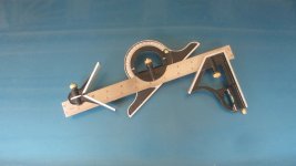
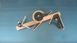
For the last 50 years I had been using an angle protractor and my "tool" to measure the caster angle but the teensy-tiny scale was awfully hard to read (picture #1). It worked but it was real clumsy to use because I had to use both of my hands to hold the tool and angle protractor in place. Several months ago I discovered magnetic base digital angle finders were available and were reasonably inexpensive at $25-$35. So a week ago I took the plunge, bought one (picture #2), and modified my tool so the magnetic base angle finder could sit on it. Now I can hang the tool AND angle finder on the ball joint's grease zerks and as I make changes to the shims the angle finder shows the amount of caster or camber change without my touching it.

As you can see it is NOT necessary to have the wheels/tires on a car to measure and set the caster and camber angles. All you need is a simple home-made tool that hangs on the grease zerks and the back side of the tool represents the caster angle (you can even see the angle with your eyes). Just stick the magnetic base angle finder on the tool and VIOLA............an easy-to-read digital display of your caster angle. Couldn't be easier or more accurate.

Over the years I have taught about a dozen people how to align their own front ends using my tried-and-true method and that's why I'm showing you guys so you can pass the knowledge on to others.
 

Attachments

  • 1971 Corvette Alignment Angle Protractor Harbor Freight $8 003.jpg
    1971 Corvette Alignment Angle Protractor Harbor Freight $8 003.jpg
    246.4 KB · Views: 102
  • Angle Finder With Digital LED Display 001.jpg
    Angle Finder With Digital LED Display 001.jpg
    246.8 KB · Views: 99
I think this would get you pretty close. At least you could be comfortable driving your car to an alignment shop after you rebuilt the front suspension and steering at home.

Tom
Agree !! with Tom..Drive to a good laser computer 4 wheel alignment shop..with shim kit for front and rear, and the specs you want.
Nick
 
A proper alignment starts with measuring and accounting for the true thrust line produced by the drive wheels. Neither the front wheel alignment or rear wheel alignment instructions posted here even mention it.
 
1. First of all you'll need to make a simple tool using 24" of 1/8" X 1" steel flat bar and buy a magnetic base digital angle finder (about $30) as shown in pictures #1 and #2. The tool is 10-1/2" tall and 5-1/2" wide (excluding the 2-1/2" long shelf for the angle finder to sit on) and with 1/4" holes drilled exactly 5" from the angle finder's side.

2. Measure the height of the center of your hub cap to the ground and it'll be about 11-1/2" to 11-3/4 (picture #3). I am running 225X60R15 tires and mine measured 11-5/8".

3. Remove the wheel and set the hub onto a 8" thick timber and shims to obtain the same height (picture #4).

7. Adjust the camber angle by adding or removing shims at the front of the control arm (picture #6 again).

So the accuracy of this depends on how accurate the tool has been made. Get one of the holes a little off or the angles on the welds a little off from 90* and it will alter your caster angle. Again for the height to the hub cap (for camber), although a little bit off won't hurt as much.

You do realise that by only adding/removing shims at the front you are altering the caster angle again? You need to add/remove shims from the front and rear equally to change camber without it altering caster.

Also your toe adjustment only alters overall toe. What if one wheel was way out before you started?

Better off getting it done at a shop.
 
Also your toe adjustment only alters overall toe. What if one wheel was way out before you started?

Better off getting it done at a shop.

Right you are. I have bumped a curb before (slid on the ice) and knocked the toe out to the point that I could feel it fighting back and forth when trying to drive straight. Only one side was off due to a slightly bent steering arm and outer tie rod end. Adjusting both sides equally makes sense if you know that all is well on both sides to begin with but how do you know that one side only hasn't been altered by a pot hole, curb or something in the road. Wouldn't adjusting both the same in a situation like this result in a steering wheel that's off center?

Tom
 
Aligning Your Own Front End

I had my '59 Chevy's front end aligned when I was about 16 years old and during the process I was puzzled over why the technician (a pimple-faced 18 year old kid) often turned the wheels from side-to-side (???). After the alignment was done I took my Chevy home and decided to see what exactly happened when the wheels were turned from side-to-side. I noticed the camber angle (the outward tilt) changed from a positive camber to a negative camber and using an angle protractor (picture #1) I discovered the positive angle exceeded the negative angle by about 2 degrees. So that's how I discovered the technician determined the caster angle by observing the differences of camber angles! Hmm. Next I put my angle protractor against the side of the wheel (with the wheels pointing straight ahead) and found it was tilted outward by about 1/2 degree. The camber angle. Hmm. I began wondering if those caster and camber angles could be measured with the wheels off and with the front end sitting at the usual height so I removed the wheels and set the bearing hub on blocks of wood and shims (like picture #2 shows) and then realized there was no way I could measure the caster angle UNLESS I made a simple tool to attach to the upper and lower ball joint's grease zerks. So using some 1/8" X 1" steel flat bar I made the tool and used my angle protractor to measure the amount of rearward tilt (the caster angle) off the back of the tool and VIOLA. It showed about 2 degrees of rearward tilt! Then I put the wheels back on and found the distance between the front of the tires was about 1/8" less than the rear of the tires (the toe in). That was about 50 years ago and I have been aligning my own front ends ever since.

"Aligning" a front end involves 3 important measurements:

1. The caster angle (the amount of rearward tilt of the ball joint center lines). It is the caster angle that makes the car go straight ahead when you release the steering wheel (on a flat road)

2. The camber angle (the outward tilt)

3. Toe in

Once you actually observe what happens to the upper ball joint's position when you add or remove shims at the upper control arms it all becomes very clear and that's why my "wheels off" method is such a good teaching tool.
 

Attachments

  • 1971 Corvette Alignment Angle Protractor Harbor Freight $8 003.jpg
    1971 Corvette Alignment Angle Protractor Harbor Freight $8 003.jpg
    246.4 KB · Views: 102
  • 1971 Corvette Front End Alignment Tools And Pictures 004.jpg
    1971 Corvette Front End Alignment Tools And Pictures 004.jpg
    247.5 KB · Views: 99
Last edited:
Status
Not open for further replies.

Corvette Forums

Not a member of the Corvette Action Center?  Join now!  It's free!

Help support the Corvette Action Center!

Supporting Vendors

Dealers:

MacMulkin Chevrolet - The Second Largest Corvette Dealer in the Country!

Advertise with the Corvette Action Center!

Double Your Chances!

Our Partners

Back
Top Bottom