dirtypants
Well-known member
alignment for late C3
Pretty much referring to C3 here...late models factory specs are better( than the old 70s specs) for sport-street, can be modified for true track. But for C3 , do some we searches..look at quite a few sites that do not just re quote factory..vbandp, Duntov and more..plenty of variations but as you look thru you will find kind of a middle concensus..and that is what I went with for an 81..OK..so here is what specidied FOR THE SHOP to use..individual results may vary..on my car, seems very good. Again, align done after new bush, wheel bearings, ride height at rear with the rear most spring bolts/and good bushes (poly if you like) shocks, etc. A nice add is the adjustable rear camber strut.
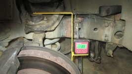
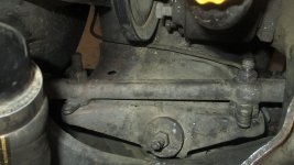
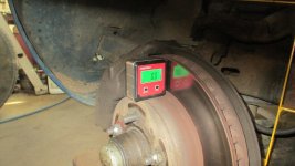
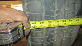
Do the rear first: rear camber .5 deg each side. then rear toe 1/16 in each side so 1/8 total (some may like less..1/32 ea). Pivot bolt to 50ft lb. It is a "pivot" and needs to move. Then do front: caster first-right side: 3.0 to 3.25 if it will go to 3.25. Somewhere in there is about max you can get., Ledt side approx .3 deg less than right (allows for crown of roads); Now front camber .29 neg both sides. Then front toe: 1/16" in each side, so total toe is 1/8" in. Subtract shims at front A armbolt to increase positive caster, and or add shims at rear bolt as needed, goal is max pos caster while maintaining toe and camber spec. No more than . 4inch diff in thickness of front front to front rear shim packs. Two threads min showing beyond nut. When front is complete, tighten to firm, back off, then lightly tighten to 15 ft lb the bolt having thinnest shim pack, then the other, then final torque thin first, var on ground, lower inner pivot bolts to 40ftlb, upper to 50 ftlb..with car on ground. Check the shops computer print out of completion for proper spec. Only slight tolerance off spec is permitted due to shim thicknesses. Steering wheel of course must be set dead straight when wheels are dead straight. But fact check me yourself see if you like these late C3 specs. Happy driving..with this set up I have no wander even on uneven or stud tire grooved roads, and dead on stuck to the road cornering,.
Nick
Pretty much referring to C3 here...late models factory specs are better( than the old 70s specs) for sport-street, can be modified for true track. But for C3 , do some we searches..look at quite a few sites that do not just re quote factory..vbandp, Duntov and more..plenty of variations but as you look thru you will find kind of a middle concensus..and that is what I went with for an 81..OK..so here is what specidied FOR THE SHOP to use..individual results may vary..on my car, seems very good. Again, align done after new bush, wheel bearings, ride height at rear with the rear most spring bolts/and good bushes (poly if you like) shocks, etc. A nice add is the adjustable rear camber strut.
Do the rear first: rear camber .5 deg each side. then rear toe 1/16 in each side so 1/8 total (some may like less..1/32 ea). Pivot bolt to 50ft lb. It is a "pivot" and needs to move. Then do front: caster first-right side: 3.0 to 3.25 if it will go to 3.25. Somewhere in there is about max you can get., Ledt side approx .3 deg less than right (allows for crown of roads); Now front camber .29 neg both sides. Then front toe: 1/16" in each side, so total toe is 1/8" in. Subtract shims at front A armbolt to increase positive caster, and or add shims at rear bolt as needed, goal is max pos caster while maintaining toe and camber spec. No more than . 4inch diff in thickness of front front to front rear shim packs. Two threads min showing beyond nut. When front is complete, tighten to firm, back off, then lightly tighten to 15 ft lb the bolt having thinnest shim pack, then the other, then final torque thin first, var on ground, lower inner pivot bolts to 40ftlb, upper to 50 ftlb..with car on ground. Check the shops computer print out of completion for proper spec. Only slight tolerance off spec is permitted due to shim thicknesses. Steering wheel of course must be set dead straight when wheels are dead straight. But fact check me yourself see if you like these late C3 specs. Happy driving..with this set up I have no wander even on uneven or stud tire grooved roads, and dead on stuck to the road cornering,.
Nick