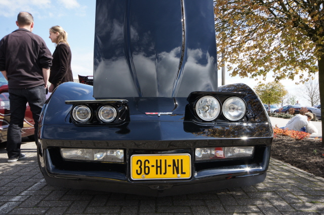
Welcome to the Corvette Forums at the Corvette Action Center!

Original L81 engine pic's..

Of course you are right! I'm whining about two lines running across the steering but I still have all the L81 junk on the engine. :D

Greetings Peter
 
Peter,

Were you able to retain head light bulb adjustability? The new shroud is coming along nicely. Good work! You are one the most patient men I know. :D
 
Hello Gerry,

Sorry for the late reply! No the original adjustment springs and stuff are gone, just made new ones but now it's more difficult and I have to remove the shroud to get to the bolts.

And just a small update on the differential.
I got the new bearingcap back from the shop. It's not idential to the example I posted but that doesn't matter. I think it looks very nice and it also fits like a glove (well as far as I can check it).
Here the bearingcap in place:

IMG_5370.JPG


IMG_5372.JPG


And a comparison between the old alu cap and the new billet cap.

IMG_5373.JPG


IMG_5374.JPG


After that I send the alu housing with battwing and posi unit with gears to the shot peener. Should give it some extra strength and it's all nice and clean. After I got all the parts back I started assembly. Wasn't as easy as I hoped it would go. Apparently the older eaton units are easier to assemble then these tru tracks. When everything was finally in place (except for the snap rings on the cross shaft) I was hoping to make it turn (as you can see in the picture) but the posi is so tight that there is no way I can make it even move on tooth. After contacting Mike and Tom both said it was normal and that I shouldn't worry about it.

IMG_5375.JPG


After that I put in the new races. It's ashame you see every durty finger on the clean alu...

IIMG_2561.jpg


IIMG_2562.jpg


Greetings Peter
 
Surely, you will cover the nice clean aloy in a good coat of clear lacker!!
Even if no-one will ever see it :D
Cor
 
And then something else.
For some time I was thinking to get another engine. Not just to buy a compleetly new engine but to calculate everything myself, buy all the parts and assemble it myself. I'm not in a hurry but it should be in my car within 4 years (as the body off took almost 10 years I think this is doable) :)

First I was thinking to build a 383. As a friend had a nice 350 roller engine for sale with a 1 piece RMS I bought that one. (previous picture) But as I was searching ebay for some head studs I came across a nice Dart SHP 400ci engine. I already knew that the Dart engine really was THE engine for me but as they aren't that cheap (I have to get it to this side of the atlantic) I never gave it much thought. But this engine had less then a hour time on it as it was checked for leaks and then boxes away. As they order was cancelled they parted out the engine and put everything on ebay. Lucky for me I was the highest bidder and also for some other stuff he was selling. After some good and quick emails back and forward I transferred the money and the enige was packed for the harbor. And now (I think a month later) I have it in my garage :upthumbs

Yes it was a nice day when the truckdriver called me that he had arrived. As I was working my father unloaded the package and I wend looking that same evening.
Well the engine really looks great, you can still see the cross markings in the cilinderwalls and it even has the white cam grease on the cam bearings, like new but with all the engine work already done!

IIMG_2563.jpg


IIMG_2564.jpg


Here the ARP head studs I was looking for in the first place and at the back a surprise from Michael (the seller) a Cloyes timing set! :D

IIMG_2565.jpg


And a ATI super damper. No more problems with the original rubber line in between the damper. It also accepts a blowergear in front of it but I'll just use it like this.

IIMG_2566.jpg


And the list goes on! A flywheel also almost brand new. Don't know how many teeth but as I also need a high torque starter that isn't a problem.

IIMG_2567.jpg


Also included a set with hellfire piston rings, they were in the engine when i ran but they are all nicely labeled with the correct cilinder number. So if I may say so, his is a damn good start! :happyanim:

And still not all. Last week I found a nice Milodon 31506 oil pan on ebay (still in plastic) but as I was the only one bidding I got it for $150 :rotfl The seller also included a Milodon 18465 pickup with 3/4 inlet. These parts are at this moment in a warehouse in Paramount waiting on my other parts.

I was looking for a good oil pump. Don't want no high volume or high pressure and with the 3/4 pickup inlet my choise is the Melling 10554. As I don't know how old the current water pump is I'm also going to order a new one for this engine the Milodon 16215. Those parts will be the next package crossing the ocean. :)

On the engine. I want it to be a torque engine as I'm not really a high rev somebody, but from time to time I still want to be able to hit 6000 rpm. As I see it now static compression will be around 9.75:1 (with iron heads and regular gas) and dynamic at 8.2:1 (thats about max I can give it when I build it myself.
The crankshaft will be a Callies Compstar, pushrods and pistons I don't know but forged steel and forged alu.
Cam and lifters Compcams (OEM roller) or something better (any suggestions?)
Heads, at this moment I have Dart Iron Eagles 180cc with 72cc combustion laying around but maybe a alu CNC head will be better for this engine. Still need to lookup the flow numbers are low lift.
Intake will be stock L81 (maybe the runners matched to the heads) or something better but I don't think there is much that will fit.
Carb will be the E4ME with some tweaks.
Exhaust already is a 2,5" true dual with x-pipe and original short tube headers. I think I'm going to change the headers in to long tubes for Stainless works. I have the time so at this moment ebay's automatic search is my friend.

What TQ and HP numbers am I looking for? Don't really care the only thing that I need is an engine so my 81 will leave my friends 86 vette far far behind! :D

That's it for now!

Greetings Peter
 
Whoops I forgot about this topic. But non the less an update! :)

To continue with the differential.
The day came to setup the differential the right way. For our 80-82 diff's there is no better guy to talk to about this then Mike Dyer (tracdogg)! The problem is to find the right resistance between the ring and pinion gears and the teeth markings.

In the below picture you see the diff hanging in the bracket I made for it. As you can see I changed all the bolts for studs and nuts.

IMG_5376.JPG


From the side:

IMG_5377.JPG


There are a few steps to take to set the teeth contact surface. First you need the check the backlash (play between ring and pinion gears). You need to check this in 3 places (1/3 from each other) play should be between 0.0050 and 0.0090" and shouldn't differ more then 0.0030"! To do this right the pinion gear also needs a preload so it doesn't move to easily. You connect the micrometer to the drive side of the gear (here I'm using a mitutoyo with 0.0001" accuracy)

IMG_5380.JPG


When backlash is within spec. After that you take the gear marking compound and put it on 4 to 5 gears in 2 different places (about opposite to each other). After that you turn the gear 5x left and 5x right. As the gears had load on them irl. A friend was helping putting load on the pinion gear. This way the marking compound shows a more accurate pattern. As I used a used ring and pinion gear set the pattern isn't as good as with a new set.
The final diff data before assembly: Pinion shim: 0.0270, Ring gear left side shims 0.0435, Right side shims 0.0430, backlash between 0.0055 and 0.0075".

IMG_5386.JPG


IMG_5387.JPG


After a phonecall with Mike he advised me to set the pinion preload to 20LBS/inch and the backlash to 0.0080" average. So I swapped some carrier shims to inlarge the backlash. From this moment I stopped checking the backlash in 3 places but turned to 9 places to get a better reading. Then a little artistic picture. Showing the diff bearings from side to the centerpin.

IMG_5390.JPG


After that I torqued the pinion gear nut to final spec. 280Nm. And the pinion gear is still turning nicely at 20LBS/inch.

IMG_5393.JPG


Installed the seals on the sides.

IMG_5397.JPG


After that we make a final check putting marking compound on all teeth and this is the result:

IMG_5398.JPG


IMG_5399.JPG


Top view:

IMG_5400.JPG


Next put everything back together. Let it sit for a day to let the gasket (and liquid gasket) dry.

Greetings Peter
 
Last edited:
And the last differential pictures:


IMG_5401.JPG


After that the job to put the diff back in the vette. Not easy with all the suspension parts and exhaust still under the vette. When the diff was in the vette I put oil in it with the special additive.

IMG_5402.JPG


The next the HID project! :D

It was a lot of sanding, filling, sanding, painting, sanding etc etc but this is the endresult of the passengers side. Still the BMW projects, ALFA bezels and custom shroud.
It only needs a final black paint job (and at that time the vette some TLC! :D)

IMG_5404.JPG


IMG_5405.JPG


At our annual first meeting of the year I put in one original headlight and the HID headlight next to each other so you can see the difference.

02380a90.jpg


Here you can see the wiring on the drivers side for the HID units. From right to left. In red the prime fuse, next the wolstentech relay and left the two fuses for each ballast on that side (of course the passengers side has the same wiring setup).

IMG_5407.JPG


Now its "just" some work to mirror everything to the drivers side. Here you can see the headlights upside down with the ignition system in place.

IMG_5408.JPG


And the last picture so far. On the drivers side also the HID system but without the custom shroud (because I still need to fabricate it)

IMG_5410.JPG


Stay tuned! :D

Greetings Peter
 
Last edited:
Truly awesome Peter!!!
 
Thanks again Kane :D

And a new update. Before I begon the restauration about 10 years ago the vacuumsystem was working fine (or so I thought) so I just replaced all the rubber vacuumlines and that was it. As one headlight wasn't opening anymore a couple of months ago I begon a system check. I found out both relays were'nt perfect and one actuator had a problem plus my vacuumtank wasn't perfectly airtight. So work begon on the relays. From this forum I got a good website that showed how to repair them yourself so here it goes.

IIMG_2583.jpg


First open up the old relay and take it apart.
(this is the website btw. Bumper Repair)

So I tried to bring the rubber back to live (as it was still very good) but it wouldn't seal properly. I then put a small revit in between the rubber so it was forced to the cilindersides. Now it works perfectly and it still slides up and down very fast!

IIMG_2584.jpg


After that I put some grease on the shaft and reassemble it. With some solder I repaired the cut ring.

IIMG_2586.jpg


IIMG_2587.jpg


So these two will hold up for some extra years.

IIMG_2588.jpg


Next I removed the OEM steeringbox and replaced it for a Borgeson unit.

IMG_5416.JPG


IMG_5417.JPG


As the Borgeson unit has the power steering inside the box I made a 8mm stainless plate to cover the big hole between the 3 steeringbox holes. Hopefully this will give it just some extra strength. I also used 1 or 2 shims to perfectly aline the steeringbox with the steering column. Here you can see the bigger Borgeson unit in place but still not connected.

IMG_5418.JPG


IMG_5419.JPG


Small tip I got from Jim Shea is to take the air out of the steering system manually (without the engine running) that way there is less change the control valve in the pump gets stuck and low rpm power steering is lost. Well it worked perfectly for me! So thanks again Jim! :thumb

And last what 4x HID looks like in the dark (no way you can beat this with standard halogen)

IMG_5422.JPG


Greetings Peter
 
Great work- I'm impressed. :upthumbs


And last what 4x HID looks like in the dark (no way you can beat this with standard halogen)

IMG_5422.JPG


Wow- that's incredible!!! :thumb
 
If I could take a picture with my HID headlights side by side with a normale C3 they difference would be much more pronounced. :)

But there is more to come, altho not that much.
First the speedometer wasn't working anymore. The drive gear clip was broken so it was pushed backward. By lowering the diff and removing the driveshaft I could remove the tailpiece to gain acces to the drive gear.

IMG_5432.JPG


So I removed the drive gear (still in a good piece) and installed the same new gear with a hollow pipe. After a couple of houres everything was back to normal.

IMG_5434.JPG


Next to do was the driverside headlight. First installed the wooden rings around the HID units.

IMG_5436.JPG


After that I just "mirrored" the other shroud.

IMG_5438.JPG


Then the same as the first, began with blue clay to close all the holes and gave a radius to all the corners. Then work with putty and sand it back down, that again and again till it is as close as I can get it.

IIMG_2841.jpg


IIMG_2842.jpg


:)

Greetings Peter
 
IMG_5375.JPG

Greetings Peter
Hey Peter, hope you don't mind that I brought this pic up but...I'm trying get a good look at your Stub Axle and it almost appears there is what looks like a black, coin type surface ontop of the actual Axle.

Question, is that black area the "hardened tip" that gets put on the axle-end by weld or press-fit? Might you have any other pictures of the tip end before you assembled?
I'm desperately trying to see what a re-man' axle looks like...and 'if' that is a Loanstar part sold by retailers...and where did u get it?
 
Sorry no black surface, it's only shade I think. I used the old yokes from the first rebuild as they only has 3000 miles on them. Back then I got them from Zip.

Greetings Peter
 
Small update on the headlight progress. Well, or Im going very slow or time is just going to fast! So far I think I'm the "problem". :D

First my ECM was/is giving me problems. The dwell meter (reading almost zero) shows the ECM is compensating for a full lean mixture (enriching the mixture) but my wide band A/F meter is showing me the mixture is already rich. No trouble codes so send the ECM to Cor to double check my findings. He also saw the same problem, a dwell meter needle hovering around 25 - 30 degrees and then just dropping to zero! So I ordered a new ECM from Rockauto, now I need to check if the dwell readings are steady or not. Looks to me like the MC solenoid signal just stops from time to time.

Then the headlight shrouds. First made the paper/clay model just like the final piece. This way it is ready to make a negative in it from polyester. Left the final shroud (sanded ready for final paint) and right the paper/clay model.

20131101_215041.jpg


This time we tried to use gelcoat between the paper/clay model and the negative. Didn't work out that great, very sticky stuff and trying to separate the clay model from the negative model we had to distroy the clay model.

IMG_5442.JPG


IMG_5443.JPG


So second change but now making the final model in the negative model.
First the normal recipe, putty sanding putty sanding etc etc so the negative model is smooth and ready.

IMG_5444.JPG


Then apply some grease on the negative model, not to much because the gelcoat needs some base to stick to. But enough grease to separate the negative model from the final model.
After that a nice layer of gelcoat. The gelcoat doesn't harden that much so when I put the polyester on it the gelcoat will bond with the polyester and will turn into a nice white layer on the outside of the final model.

IMG_5445.JPG


Polyester stuff on it and wait a few hours to let it cure.

IMG_5446.JPG


After a few hours (when the polyester isn't fully cured) the separation begins. As the polyester is still somewhat flexable it's easier to get it out of the negative model. Or at least, that was the plan... After 3 hours working on it with screwdrivers, puttyknives and other stuff they were still bonded together! In the mean time i distroyed the gelcoat as I tried to separate the two. The next day a friend tried to take them apart, still no way! So in the end the only thing we could think of was to grind the final model into pieces to save the negative.

IMG_5447.JPG


In the above picture you can see the gelcoat still sticked to the middle part of the model and in other places the smooth surface is pretty much distroyed! So back to the putty, sanding action. After a week the negative model was back where we started..

IMG_5448.JPG


Our conclusion, gelcoat is nice for big and simple models but not these small the heavily curved things. So next time no gel coat!
Then time to escape christmas and new year. 16 days Thailand with friends, sun, beach, scubadiving, jungle tracking, hell of a way to get from 2013 to 2014! :beer

Then last week, back in Holland second change to make the final model. This time only loads of grease in the negative model. An extra layer polyester to make it extra thick. This time after 3 hours the outside was solid and wasn't sticky anymore, so with two putty knives I took the final model out of the negative without to much problems.

IIMG_3095.jpg


On the left still the final product (sanded for final paint) and on the right the driversside final model (still with alot of work to do)

IIMG_3096.jpg


So hopefully the headlights will be finished around februari so I can take it to the painter.

Greetings Peter
 
Another update on the headlights but this time with the end product! :happyanim:

As the model wasn't perfect I fabricated some extra polyester left and right.

IMG_5452.JPG


And then after houres of sanding and putty ready for painting (first round)

IMG_5453.JPG


First layer paint was white. Very think so I could sand all the ups and downs out of it. After that 2 layers 2 component black, sanding it with 400. After that it looks like this before the final paint job.

IMG_5456.JPG


You can still see some small reflective black dots (low points). This is as perfect as I can make it. With the new paint layer there is no way you can see the low spots.

IMG_5457.JPG


After this I test fitted the assembly. Seems like the alu headlight piece wasn't perfectly as it was below the body at the rightfront. We had to give it a 2 to 3mm putty layer in the right corner to make it fit perfectly. And when you're busy with putty why not check the other piece to see if it is good enough. Well, yes again sanding putty sanding putty. Will it ever stop? ;)

So THIS IS IT!
I have to say, it took a while and some hours. But I'm very happy with the result and also proud!
With the lights on:

IMG_5468.JPG


The light changes color from blue to white to "little yellow" white. When the lights get older (and more hours) they change back to blue-ish. You can see that the left ones are yellowish white and the right one more blue-ish white. At the end they should all be the same blue. New model lights don't change color anymore.

And lights off:

IMG_5473.JPG


IMG_5476.JPG


IMG_5478.JPG


Next on the list. Tomorrow a car wash to remove the dust and Monday time to do a complete polishing job! The carb is still at full rich but my new hypertech chip is on its way. Next weeks sunday it's the first meeting I'll attend :)

Greetings Peter
 
Nice!!, but I said that before. :cool!:
What I really wanted to say now is: don't waste your sunday washing your car, it is such excellent weather now, take this beauty for a long spin !!
Enjoy,
Cor
 
@Cor, are you stalking me? ;LOL:gap

Driving it is a great idea but next time I think.

Greetings Peter
 
No problem Cor, it's just that I had imagined my first groupie to be somebody else... :D

Took her for a spin last night. Still need to put all the lights at the same height. With the hid cut off plate you can clearly see if one or more are to low or to high.

Greetings Peter
 

Corvette Forums

Not a member of the Corvette Action Center?  Join now!  It's free!

Help support the Corvette Action Center!

Supporting Vendors

Dealers:

MacMulkin Chevrolet - The Second Largest Corvette Dealer in the Country!

Advertise with the Corvette Action Center!

Double Your Chances!

Our Partners

Back
Top Bottom