- Thread starter
- #41
Navigation
Install the app
How to install the app on iOS
Follow along with the video below to see how to install our site as a web app on your home screen.
Note: This feature may not be available in some browsers.
More options
Style variation
You are using an out of date browser. It may not display this or other websites correctly.
You should upgrade or use an alternative browser.
You should upgrade or use an alternative browser.
Question: Will the Edelbrock Pro Fo XT fit under an 84 Hood?
- Thread starter AussieCorvetteNut
- Start date

- Thread starter
- #42
AussieCorvetteNut
Well-known member
Early Morming Start - Sunday 3:30am
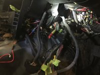
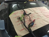
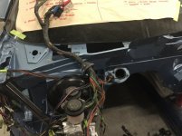
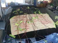
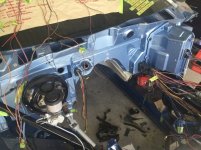
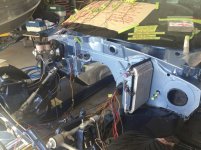
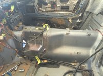
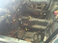
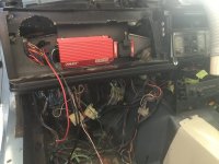
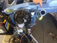
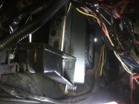
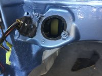
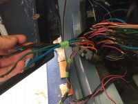
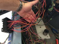
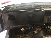
Got up early this morning and removed the ECM Harness from the car.
Removed all the engine management harness from it, only left the gauge stuff really, oil pressure, speedo, coolant temp etc.
Found a kill switch wired disabling the fuel injectors.
The first photo shows a Nikko pen when the factory ECM is installed horizontally.
Photo 2 shows the RHD cabin.
Photo 3 & 4 are the ECM harness removed from the car.
Photo 5 is the cutdown version of the ECM harness after 6 hours of careful labelling and sorting.
Photo 6 & 7 show a cleaner firewall.
Photo 8 is showing the trans tunnel. The selector box needs to be cut out and plated to allow for the Tremec.
Attachments

Last edited:
- Thread starter
- #43
AussieCorvetteNut
Well-known member
- Thread starter
- #44
AussieCorvetteNut
Well-known member
- Thread starter
- #45
AussieCorvetteNut
Well-known member
Keep the factory ECM or Shelve it?
I have been studying the FSM Electrical Wiring Diagrams and I would like to remove the factory ECM.
I think it may cause issues later.
As I am fitting a FAST ECM that will control the Edelbrock PRO FLO XT, I am starting to look at the idea of total removal of the factory ECM.
The FSM is saying that the ECM does not power the digital dash, the digital dash is stand alone, but there are signals sent back to the ECM to calculate AVG MPG etc.
My concern is that some of the wiring does connect to the ECM and runs back through to the connectors on another harness.
This harness connects to the guages and centre cluster drive rinfor display.
I have disconnected the manual transmission ball switch wires and the two CF Injector wires from the ECM engine bay harness.
The FAST ECU will control spark advance, cooling fans. Fuel pump relay will need to be adjusted.
I amanged to get onto a company here in Australia that prints on auto wire, so I have punk wires with black or white stripes for example. At least I will be able to add the correct colour combos back in and not just solder aftermarket wire into the harness.
I have to clean up my fuse box, so the pink and white stripe wires will tidy that up.
Any thoughts on bypassing the ECM?
- Thread starter
- #46
AussieCorvetteNut
Well-known member
- Thread starter
- #47
AussieCorvetteNut
Well-known member

- Thread starter
- #48
AussieCorvetteNut
Well-known member
Update....
Hi Everyone,
Thought I would post an update on the progress of the Pro Flo XT Install.
This will be a long winded post as I am rebuilding everything as I go.
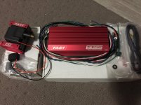
The FAST EZ EFI ECM wiring harness and MPFI Harness are all laid out on the Vette while I work through the old ECM Harness and what is needed.
As the old ECM won't really power anything, I am looking at disconnecting it.
I am working through multiple tasks and issues as I go, like fabrication of the air filter assembly by using a conbination or 84 and 85 parts. As the TPI Vettes have a similar air intake location as the Pro Flo, it makes sense to use the factory bits.
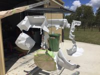
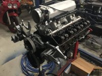
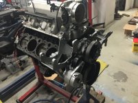
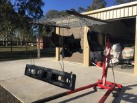
I have sourced a set of serpentine brackets to suit 85 to 87, blasted them in the cabinet and sprayed them up with aluminium paint. Check the photos out!
The photos are of a mock up, my heads will be RHS Heads to suit the higher lift of the Comp Cam specs with 1.6:1 rockers.
I had a mate of mine bring his 85 around and I got out the kids play-dough and put it on the TPI unit in his car.
Dropped the hood and then got the measuring stuff out...she is going to be a tight fit!

Tony
Hi Everyone,
Thought I would post an update on the progress of the Pro Flo XT Install.
This will be a long winded post as I am rebuilding everything as I go.
The FAST EZ EFI ECM wiring harness and MPFI Harness are all laid out on the Vette while I work through the old ECM Harness and what is needed.
As the old ECM won't really power anything, I am looking at disconnecting it.
I am working through multiple tasks and issues as I go, like fabrication of the air filter assembly by using a conbination or 84 and 85 parts. As the TPI Vettes have a similar air intake location as the Pro Flo, it makes sense to use the factory bits.
I have sourced a set of serpentine brackets to suit 85 to 87, blasted them in the cabinet and sprayed them up with aluminium paint. Check the photos out!
The photos are of a mock up, my heads will be RHS Heads to suit the higher lift of the Comp Cam specs with 1.6:1 rockers.
I had a mate of mine bring his 85 around and I got out the kids play-dough and put it on the TPI unit in his car.
Dropped the hood and then got the measuring stuff out...she is going to be a tight fit!
Tony
Attachments
- Moderator
- #49
- Thread starter
- #50
AussieCorvetteNut
Well-known member
No smog requirements
Hi Kane,
Nah...we are lucky here in Australia that we don't have any smog requirements like the U.K or USA.
I have just purchased my air pump eliminator from one of the local Corvette Mechanics in Brisbane, he uses a billet pulley as opposed to a plastic pulley.
85+ cars fitted with a Cat must have a cat re-installed, my 84 won't have cats and can be more aggressive in the exhaust system.
I just have to get an o2 sensor plug welded for the FAST EFI and we are good to go.
Wow- looks really, really good!
Are you running any emissions- such as the smog pump? You may have mentioned and I forgot. LOL
Sent from my iPhone using Tapatalk
Hi Kane,
Nah...we are lucky here in Australia that we don't have any smog requirements like the U.K or USA.
I have just purchased my air pump eliminator from one of the local Corvette Mechanics in Brisbane, he uses a billet pulley as opposed to a plastic pulley.
85+ cars fitted with a Cat must have a cat re-installed, my 84 won't have cats and can be more aggressive in the exhaust system.
I just have to get an o2 sensor plug welded for the FAST EFI and we are good to go.
Last edited:
- Thread starter
- #51
AussieCorvetteNut
Well-known member
Update - Moving slowly along
Hi Everyone,
Thought I would post an update on the progress of the Edelbrock Pro Flo XT Install.
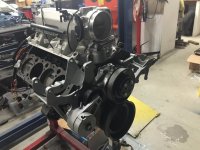
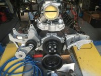
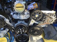
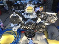
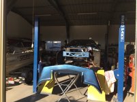
I purcased an air pump delete pulley frm one of the Corvette Mechanics in Brisbane, he uses a billet pulley instead of the plastc one.
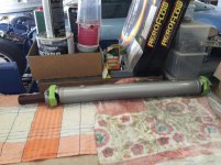
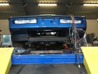
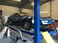
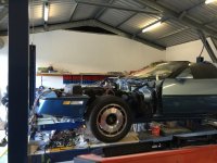
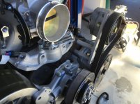
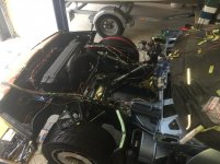
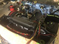
The photos show the mock up of the serpentine system, to allow a front air feed similar to a TPI system.
Note the thermostat housing, there is less than 50mm between the Pro Flo's Intake and the bottom of the throttle body, so a swivel housing can't be used, they are 77mm tall even the lowest ones.
The plan here is to use 3 x 90 degree bends and maybe a 35 degree bend in the top hose to get it on the radiator outlet...Dewitts of course.
I am installing the front TPI section of the radiator shroud to run a front mount air filter, but the bottom of this does not match an 84 air dam, so I am about to fabricate some aluminium plate to join the two.
Man, I am happy with the paint...it came out pretty good for novice.
Hi Everyone,
Thought I would post an update on the progress of the Edelbrock Pro Flo XT Install.
I purcased an air pump delete pulley frm one of the Corvette Mechanics in Brisbane, he uses a billet pulley instead of the plastc one.
The photos show the mock up of the serpentine system, to allow a front air feed similar to a TPI system.
Note the thermostat housing, there is less than 50mm between the Pro Flo's Intake and the bottom of the throttle body, so a swivel housing can't be used, they are 77mm tall even the lowest ones.
The plan here is to use 3 x 90 degree bends and maybe a 35 degree bend in the top hose to get it on the radiator outlet...Dewitts of course.
I am installing the front TPI section of the radiator shroud to run a front mount air filter, but the bottom of this does not match an 84 air dam, so I am about to fabricate some aluminium plate to join the two.
Man, I am happy with the paint...it came out pretty good for novice.
Attachments
Last edited:
- Moderator
- #52
- Joined
- Nov 9, 2000
- Messages
- 7,568
- Location
- Edgerton, Ohio, United States
- Corvette
- 1959 black 270hp (9/2/69), 1981 Beige L81(10/20/80)
Looks good. Nice work.
Tom
Tom
- Thread starter
- #53
AussieCorvetteNut
Well-known member
Getting Closer
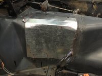
Update on the progress...
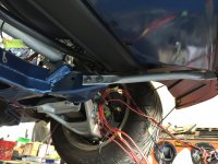
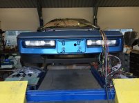
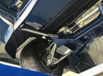
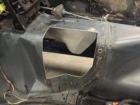
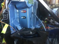
1: Customised the radiator intake to merge an 84 air dam to an 85 radiator front shroud piece to run an 85 air intake
2: Spray painted the bumper mount after a rebuild
3: Cut out the DNE transmission selector, customised the patch panel for it and sprayed in 2k paint
4: Installed battery firewall feed through a to run a seperate power supply for the FAST EZ EFI ECU and the FAST Ignition Box. This multi-point system will run the Edelbrock PRO FLO XT
Ordered all the AN fuel line fittings for the factory fuel line conversion to AN, running a FAST fuel pressure regulator, FAST filter and fuel pressure sensor.
Also converting the steering pump and rack to AN fittings to tidy the fluid transfer lines up.
��
Update on the progress...
1: Customised the radiator intake to merge an 84 air dam to an 85 radiator front shroud piece to run an 85 air intake
2: Spray painted the bumper mount after a rebuild
3: Cut out the DNE transmission selector, customised the patch panel for it and sprayed in 2k paint
4: Installed battery firewall feed through a to run a seperate power supply for the FAST EZ EFI ECU and the FAST Ignition Box. This multi-point system will run the Edelbrock PRO FLO XT
Ordered all the AN fuel line fittings for the factory fuel line conversion to AN, running a FAST fuel pressure regulator, FAST filter and fuel pressure sensor.
Also converting the steering pump and rack to AN fittings to tidy the fluid transfer lines up.
��
Attachments

Last edited:
- Thread starter
- #54
AussieCorvetteNut
Well-known member
Power Steering Pump & Fuel Pump Relay Questions
Hi Everyone,
I have a couple of questions regarding the Power Steering Pump inlet side (non-pressurised barb fitting) and the fuel Pump Relay.
Power Steering Pump:
Has anyone ever cut off the barbed end of the power steering pump inlet and flared it for AN fittings (37 degree)?
Fuel Pump Relay:
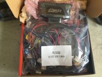
As my OEM ECM will not be triggering the fuel pump circuit, that will be managed by the FAST EZ EFI 2.0 Multipoint System (30404), and I am tidying up four other relays in the engine bay by installing them in a Hella Mini Relay Holder, I am thinking as I have room for 8 mini relays, one of these could be for the fuel pump relay.
Has anyone changed the factory OEM relay for say a Bosch/ Tyco relay.
Now I know the OEM one is pretty good and still available ( I have two) but it won't fit in the relay holder.
Appreciate your thoughts.
Tony
Hi Everyone,
I have a couple of questions regarding the Power Steering Pump inlet side (non-pressurised barb fitting) and the fuel Pump Relay.
Power Steering Pump:
Has anyone ever cut off the barbed end of the power steering pump inlet and flared it for AN fittings (37 degree)?
Fuel Pump Relay:
As my OEM ECM will not be triggering the fuel pump circuit, that will be managed by the FAST EZ EFI 2.0 Multipoint System (30404), and I am tidying up four other relays in the engine bay by installing them in a Hella Mini Relay Holder, I am thinking as I have room for 8 mini relays, one of these could be for the fuel pump relay.
Has anyone changed the factory OEM relay for say a Bosch/ Tyco relay.
Now I know the OEM one is pretty good and still available ( I have two) but it won't fit in the relay holder.
Appreciate your thoughts.
Tony
- Moderator
- #55
KANE
Moderator
- Joined
- Mar 2, 2002
- Messages
- 3,244
- Location
- KY
- Corvette
- Dark Blue 1982 Trans Am(s): Polo Green 1995 MN6
Tony- I have sectioned hard line plenty of times. I would see no reason you couldn't use AN fittings.
I assume you have a flaring kit.")
If not, you can find them reasonably priced and a good one will last forever.
Just make sure you use the right hose, it has the right pressure rating, and is resistant to ps fluid. You know this though.
Great progress - keep the updates coming!
Sent from my iPhone using Tapatalk
I assume you have a flaring kit.
If not, you can find them reasonably priced and a good one will last forever.
Just make sure you use the right hose, it has the right pressure rating, and is resistant to ps fluid. You know this though.
Great progress - keep the updates coming!
Sent from my iPhone using Tapatalk
- Thread starter
- #56
AussieCorvetteNut
Well-known member
Thanks Kane
Hi Kane,
Thanks for chiming in, the help is appreciated.
Yeah I have a 37 degree flaring tool coming.
I measured the inside diameter of the OEM P/S Pump inlet and got around 12.5mm (1/2"), I just have to double check the measurements as it is either -8AN or -10AN, and then buy the fitting.
The P/S Fluid reservoir (haven't got it yet) has -6AN return (from the rack) and -10AN feed to the pump.
Anyway, the P/S Hose I am looking at has an operating pressure of 2500 PSI and will burst around 8000 PSI.
Thanks Tony
Tony- I have sectioned hard line plenty of times. I would see no reason you couldn't use AN fittings.
I assume you have a flaring kit.
If not, you can find them reasonably priced and a good one will last forever.
Just make sure you use the right hose, it has the right pressure rating, and is resistant to ps fluid. You know this though.
Great progress - keep the updates coming!
Sent from my iPhone using Tapatalk
Hi Kane,
Thanks for chiming in, the help is appreciated.
Yeah I have a 37 degree flaring tool coming.
I measured the inside diameter of the OEM P/S Pump inlet and got around 12.5mm (1/2"), I just have to double check the measurements as it is either -8AN or -10AN, and then buy the fitting.
The P/S Fluid reservoir (haven't got it yet) has -6AN return (from the rack) and -10AN feed to the pump.
Anyway, the P/S Hose I am looking at has an operating pressure of 2500 PSI and will burst around 8000 PSI.
Thanks Tony
Attachments
Last edited:
- Thread starter
- #57
AussieCorvetteNut
Well-known member
Question - Fuel Supply & Return Lines
Okay, now I am a little worried.
I went into a speed shop yesterday to pick up some fittings.
I told the guy I had a 3/8 feed line and a 5/16 return line and he said I would need to change the return line to the same size as the feed line... ad
ad
He said it would build pressure.
I don't know if I agree with that as I have an 85 to 87 fuel pump and sender unit (TPI) and it has 3/8 feed and 5/16 return.
I am pretty sure that this was changed with the later C4's but it wasn't an issue for Chev back in the day.
I am running a FAST fuel pressure regulator on the return line and it will also have an analogue gauge.
I am also running the FAST fuel pressure sensor in the line as well, this connects to the ECU.
Now both 3/8 and 5/16 convert to -6AN fittings, so I am converting both lines on the chassis rail to -6AN.
Can anyone see an issue with this set up or the return line?
Okay, now I am a little worried.
I went into a speed shop yesterday to pick up some fittings.
I told the guy I had a 3/8 feed line and a 5/16 return line and he said I would need to change the return line to the same size as the feed line...
adHe said it would build pressure.
I don't know if I agree with that as I have an 85 to 87 fuel pump and sender unit (TPI) and it has 3/8 feed and 5/16 return.
I am pretty sure that this was changed with the later C4's but it wasn't an issue for Chev back in the day.
I am running a FAST fuel pressure regulator on the return line and it will also have an analogue gauge.
I am also running the FAST fuel pressure sensor in the line as well, this connects to the ECU.
Now both 3/8 and 5/16 convert to -6AN fittings, so I am converting both lines on the chassis rail to -6AN.
Can anyone see an issue with this set up or the return line?
- Thread starter
- #58
AussieCorvetteNut
Well-known member
HELP - Fuel Pump Fuse Circuit
Hi Everyone,
Been a while since I posted an update on the Edlebrock Pro Flo install, I have been busy with fabricating mounting brackets for hardware and researching wiring diagrams.
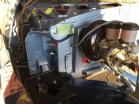
I have installed the FAST E6 Ignition Module and E92 Ignition Coil behind the dash on the passengers side (not yet wired). I fabricated a plate out of aluminium and mounted it via some brackets to the aluminium cross bar that is behind the dash.
Initially I installed an MSD firewall coil feed through under the brake booster, but changed my mind after emailing the technicians at FAST. I wasn't happy with the location anyway as it meant that the coil wire would cross the path of the ECU harness. FAST recommend an 18" distance between the noisy circuits and the FAST ECU. I moved this feed through over to the passengers side, so now the coil feed through, ignition module and ignition coil are on the passengers side and the FAST ECU is on the drivers side near the transmission tunnel. I fabricated a mounting bracket for it to sit close to a bulkhead hole that that was used for the engine wiring harness.
This will be used for the FAST ECU Engine Harness and sealed by their supplied harness grommet.
The FAST ECU Harness has been modified slightly. The ignition is on the inside of the cabin, so I have had to run these wires back through the firewall grommet. NOS wiring harness is not usedL), the CAN Links and a few others are not used, so don't need to be in the engine bay, poked them back through. Only have the fuel pump harness and trigger, the O2 sensor harness, the Fuel Pressure Sensor Block Harness and Engine Intake Pigtail run through. The Engine Pigtail plugs into a MPFI harness with the Injectors/MAP/ IAC/ Temp etc.
I have also run a few guage wires through for Oil Pressure (gauge), Engine Coolant (gauge), Oil Temp.
As we know, the digital dash has its own processor and runs separately from the ECU, although the ECU does supply MPG and Trip info...I won't need this, if the tanks says it needs gas then I'll pull in and grab the 98!
I have installed the Dakota Digital Speedo Interface Module that will convert the signal from the Tremec TKO 600.
I have also put a Dakota Digital Tach Interface Module on the shopping list.
FAST says that the E6 doesn't have a Tach feed, but the wiring diagram says that the green wire is a 12v square wave engine signal that can be used to control a Tach... I think someone didn't read the script.
The hole I made from the coil feed through is now part of a bracket system to hold a RAM Hydraulic Clutch Adjuster, so now the master feeds the clutch adjuster on its way to the hydraulic throughout bearing from RAM...best way to fix a stuff up!
I have installed the FAST EZ EFI 2.0 ECU, but not wired it yet.
I have installed a POSITIVE and NEGATIVE terminal firewall feed through to directly supply the E6 Ignition (ground will be to the engine block). I was planning to run the ECU from this feed as well, but FAST recommended not to introduce a terminal in the supply feed as it could cause issues, voltage drop etc.
I have run the battery wires with the FAST harness, but I am not happy about the single fuse in the battery feed of this wire, I am trying to keep from adding isolated fuses and relays to my project, to keep things tidy and this isolated fuse just looks crap.
I have even taken the time to route wiring to a 'gang relay holder' and then wired back so that I don't have relays scattered throughout the engine bay.
I spent 12 hours on Saturday fixing my fuse box. When the guys here did the right hand drive conversion, they modified the dash harness and where they had to extend, the used generic wire, that was not colour coded like the factory and used back to back insulation tape...WTF?
I was lucky enough to have purchased a dash wiring harness from a Corvette Parts supplier in Melbourne. I thought about it and then carefully cut the fuse panel and extra colour coded wire from the donor harness to install in 'Blue'. This eliminated the dodgy wiring, soldering and insulation tape. As this eliminated the patch wiring, it took the two joins in each wire and repalced it with one...I also used heat shrink on all soldered joints...much better.
Now, I have removed the old 84 ECU wiring harness and have worked my way back through it, electrically isolated wires that are not needed as some of the harness will be re-installed as it is connected via multiple pigtails...still looking into this though.
I am now stuck with what to do with the oil pressure switch and oil pressure sender (gauge) circuits and the fuel pump circuit as I will need to add wiring for these to the FAST Engine Bay harness.
FAST have given basic wiring diagrams for the fuel pump, engine cooling fan, but they are basic diagrams and don't include wiring in the oil pressure switch or the A/C relay circuits that are involved. The FAST ECU controls the fuel pump.
I would like to use the Fuel Pump Fuse in the panel, but the wiring diagram FAST has says direct battery feed to a fuse, then a NC Relay, triggered by the FAST Fuel Pump wire (green) and a 12v switched source.
Now if I could use the factory fuse, from this fuse the circuit runs to the fuel pump and sender in the tank. Any ideas????
FAST also have a wiring diagram for the engine cooling fan as the FAST ECU can control two fans, I like this as it uses the coolant sensor in the Edlebrock Pro Flo Intake for the signal, you set when you want the fan to come on and off...very nice.
There is also an A/C wire coming from the FAST ECU harness, that triggers that the A/C has been turned on, kicks the fans on and the engine idle is kicked up a little.
Looking at the FSM Wiring Supplement I have, the Fuel Pump Relay is directly fed from the battery and so is the Engine Cooling Fan Relay, while the triggers come from elsewhere.
Should I just run a new supply, I can use my battery terminal firewall feed throughs.
Maybe I am just over analysing it...
If I have been a bit negative against FAST, please understand that this is not the case...everytime I have emailed, someone has emailed right back with the answers I need...service is fantastic.
I will post some happy snaps soon...
Any tips are appreciated, thanks Tony
Hi Everyone,
Been a while since I posted an update on the Edlebrock Pro Flo install, I have been busy with fabricating mounting brackets for hardware and researching wiring diagrams.
I have installed the FAST E6 Ignition Module and E92 Ignition Coil behind the dash on the passengers side (not yet wired). I fabricated a plate out of aluminium and mounted it via some brackets to the aluminium cross bar that is behind the dash.
Initially I installed an MSD firewall coil feed through under the brake booster, but changed my mind after emailing the technicians at FAST. I wasn't happy with the location anyway as it meant that the coil wire would cross the path of the ECU harness. FAST recommend an 18" distance between the noisy circuits and the FAST ECU. I moved this feed through over to the passengers side, so now the coil feed through, ignition module and ignition coil are on the passengers side and the FAST ECU is on the drivers side near the transmission tunnel. I fabricated a mounting bracket for it to sit close to a bulkhead hole that that was used for the engine wiring harness.
This will be used for the FAST ECU Engine Harness and sealed by their supplied harness grommet.
The FAST ECU Harness has been modified slightly. The ignition is on the inside of the cabin, so I have had to run these wires back through the firewall grommet. NOS wiring harness is not used
L), the CAN Links and a few others are not used, so don't need to be in the engine bay, poked them back through. Only have the fuel pump harness and trigger, the O2 sensor harness, the Fuel Pressure Sensor Block Harness and Engine Intake Pigtail run through. The Engine Pigtail plugs into a MPFI harness with the Injectors/MAP/ IAC/ Temp etc.I have also run a few guage wires through for Oil Pressure (gauge), Engine Coolant (gauge), Oil Temp.
As we know, the digital dash has its own processor and runs separately from the ECU, although the ECU does supply MPG and Trip info...I won't need this, if the tanks says it needs gas then I'll pull in and grab the 98!
I have installed the Dakota Digital Speedo Interface Module that will convert the signal from the Tremec TKO 600.
I have also put a Dakota Digital Tach Interface Module on the shopping list.
FAST says that the E6 doesn't have a Tach feed, but the wiring diagram says that the green wire is a 12v square wave engine signal that can be used to control a Tach...
I think someone didn't read the script.The hole I made from the coil feed through is now part of a bracket system to hold a RAM Hydraulic Clutch Adjuster, so now the master feeds the clutch adjuster on its way to the hydraulic throughout bearing from RAM...best way to fix a stuff up!
I have installed the FAST EZ EFI 2.0 ECU, but not wired it yet.
I have installed a POSITIVE and NEGATIVE terminal firewall feed through to directly supply the E6 Ignition (ground will be to the engine block). I was planning to run the ECU from this feed as well, but FAST recommended not to introduce a terminal in the supply feed as it could cause issues, voltage drop etc.
I have run the battery wires with the FAST harness, but I am not happy about the single fuse in the battery feed of this wire, I am trying to keep from adding isolated fuses and relays to my project, to keep things tidy and this isolated fuse just looks crap.
I have even taken the time to route wiring to a 'gang relay holder' and then wired back so that I don't have relays scattered throughout the engine bay.
I spent 12 hours on Saturday fixing my fuse box. When the guys here did the right hand drive conversion, they modified the dash harness and where they had to extend, the used generic wire, that was not colour coded like the factory and used back to back insulation tape...WTF?
I was lucky enough to have purchased a dash wiring harness from a Corvette Parts supplier in Melbourne. I thought about it and then carefully cut the fuse panel and extra colour coded wire from the donor harness to install in 'Blue'. This eliminated the dodgy wiring, soldering and insulation tape. As this eliminated the patch wiring, it took the two joins in each wire and repalced it with one...I also used heat shrink on all soldered joints...much better.
Now, I have removed the old 84 ECU wiring harness and have worked my way back through it, electrically isolated wires that are not needed as some of the harness will be re-installed as it is connected via multiple pigtails...still looking into this though.
I am now stuck with what to do with the oil pressure switch and oil pressure sender (gauge) circuits and the fuel pump circuit as I will need to add wiring for these to the FAST Engine Bay harness.
FAST have given basic wiring diagrams for the fuel pump, engine cooling fan, but they are basic diagrams and don't include wiring in the oil pressure switch or the A/C relay circuits that are involved. The FAST ECU controls the fuel pump.
I would like to use the Fuel Pump Fuse in the panel, but the wiring diagram FAST has says direct battery feed to a fuse, then a NC Relay, triggered by the FAST Fuel Pump wire (green) and a 12v switched source.
Now if I could use the factory fuse, from this fuse the circuit runs to the fuel pump and sender in the tank. Any ideas????
FAST also have a wiring diagram for the engine cooling fan as the FAST ECU can control two fans, I like this as it uses the coolant sensor in the Edlebrock Pro Flo Intake for the signal, you set when you want the fan to come on and off...very nice.
There is also an A/C wire coming from the FAST ECU harness, that triggers that the A/C has been turned on, kicks the fans on and the engine idle is kicked up a little.
Looking at the FSM Wiring Supplement I have, the Fuel Pump Relay is directly fed from the battery and so is the Engine Cooling Fan Relay, while the triggers come from elsewhere.
Should I just run a new supply, I can use my battery terminal firewall feed throughs.
Maybe I am just over analysing it...
If I have been a bit negative against FAST, please understand that this is not the case...everytime I have emailed, someone has emailed right back with the answers I need...service is fantastic.
I will post some happy snaps soon...
Any tips are appreciated, thanks Tony
- Thread starter
- #59
AussieCorvetteNut
Well-known member
Some happy snaps...
Some happy snaps...
Some happy snaps...
Attachments
- Thread starter
- #60
AussieCorvetteNut
Well-known member
Similar threads
- Replies
- 0
- Views
- 57
- Replies
- 0
- Views
- 1K
- Replies
- 1
- Views
- 2K
Corvette Forums


Supporting Vendors
Dealers:

